Mastering Transient and Oscillating Circuits
LR Circuits
An LR Circuit consists of a resistor ($R$) and an inductor ($L$) connected in series. In these circuits, the current does not change instantaneously. Just as mass resists changes in velocity (inertia), an inductor resists changes in current due to Lenz's Law.
The Inductor's Behavior
To analyze specific moments in time, we use boundary conditions based on the fact that the current through an inductor cannot change abruptly:
- At $t = 0$ (immediately after closing the switch): An uncharged inductor opposes the new current entirely. It acts as an Open Circuit (infinite resistance). The current $I_0 = 0$.
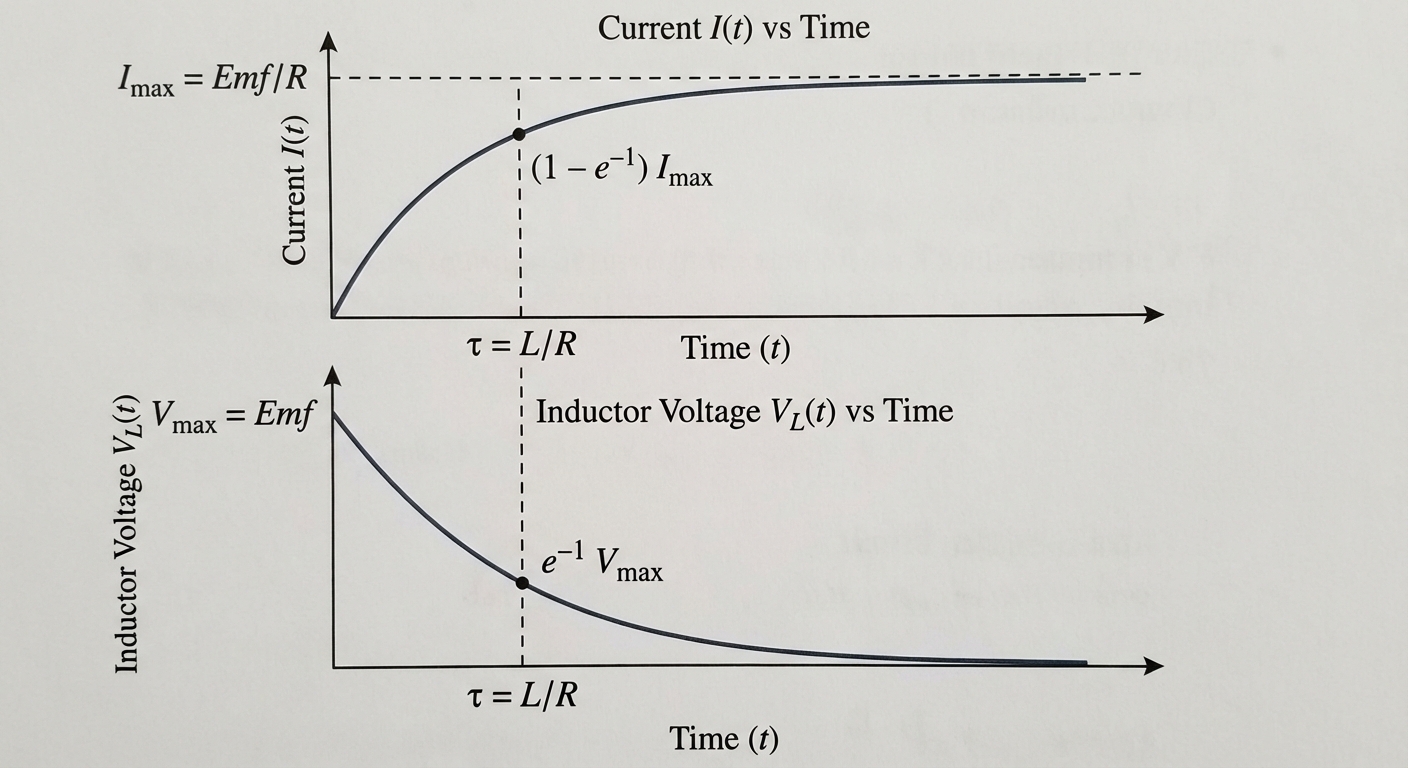
- At $t \to \infty$ (Steady State): The current is constant ($di/dt = 0$), so the induced EMF is zero. The inductor acts as a Short Circuit (plain wire). The current is determined solely by Ohm’s Law: $I_{max} = \frac{\mathcal{E}}{R}$.
Charging Phase (Growth of Current)
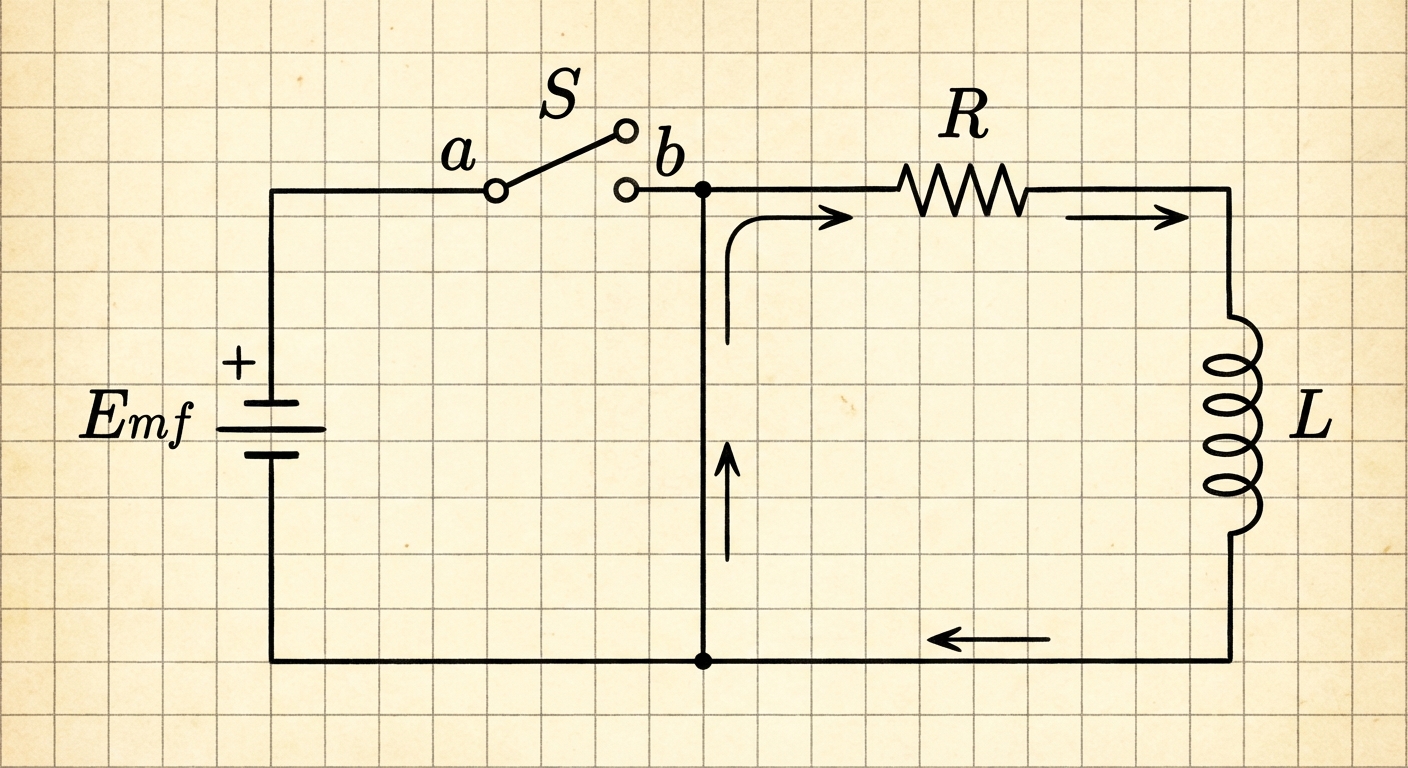
When a battery with EMF $\mathcal{E}$ is connected to a series LR circuit, Kirchhoff's Loop Rule gives:
Rearranging to solve for the rate of change of current, we get a first-order differential equation. Through separation of variables and integration, we derive the current as a function of time:
Here, $\tau$ is the Inductive Time Constant.
The Time Constant ($\tau$)
The time constant dictates how fast the circuit reaches steady state. For LR circuits:
- Unit: Seconds (s)
- Meaning: At $t = \tau$, the current has reached approx. 63% of its maximum value.
Voltage Across Components
While current increases exponentially, the voltage across the inductor drops exponentially as the opposition to current flow decreases:
Discharging Phase (Decay of Current)
If the battery is removed and the loop is closed (discharge through the resistor):
- The inductor tries to keep the current flowing in the same direction.
- The loop rule becomes: $0 - IR - L\frac{di}{dt} = 0$.
The current decays exponentially:
Energy in an LR Circuit
The battery does work to push charges. This energy is dissipated by the resistor as heat and stored in the inductor's magnetic field.
- Power delivered by battery: $P = \mathcal{E}I$
- Rate of energy dissipation ($R$): $P_R = I^2R$
- Rate of energy storage ($L$): $P_L = LI\frac{di}{dt}$
Total Magnetic Potential Energy ($UL$) stored:
LC Circuits and Oscillations
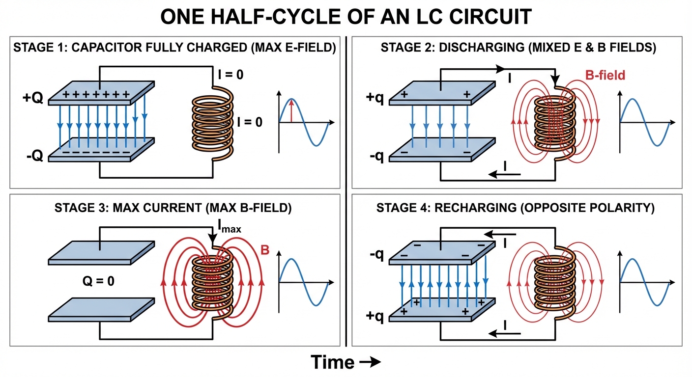
An LC Circuit contains a charged capacitor ($C$) and an inductor ($L$) with negligible resistance. This system exhibits Simple Harmonic Motion (SHM), oscillating energy between the electric field of the capacitor and the magnetic field of the inductor.
Conceptual Cycle
Imagine a capacitor is fully charged ($Q_{max}$) and the switch is closed at $t=0$:
- Start ($t=0$): All energy is electric ($U_E = \frac{1}{2} \frac{Q^2}{C}$). Current $I=0$.
- Discharging: Capacitor discharges, creating current. $UE$ decreases, $UB$ increases.
- Equilibrium ($Q=0$): Capacitor is empty ($UE=0$). Current is maximum ($I{max}$). All energy is magnetic ($U_B = \frac{1}{2}LI^2$).
- Recharging: The inductor opposes the drop in current, forcing charges onto the opposite plate of the capacitor. $UB$ decreases, $UE$ increases.
Mathematical Analysis
Using Kirchhoff's Loop Rule (sum of voltages is zero):
Since $i = \frac{dq}{dt}$, then $\frac{di}{dt} = \frac{d^2q}{dt^2}$. Substituting this yields the standard harmonic oscillator differential equation:
Solution: Charge and Current Functions
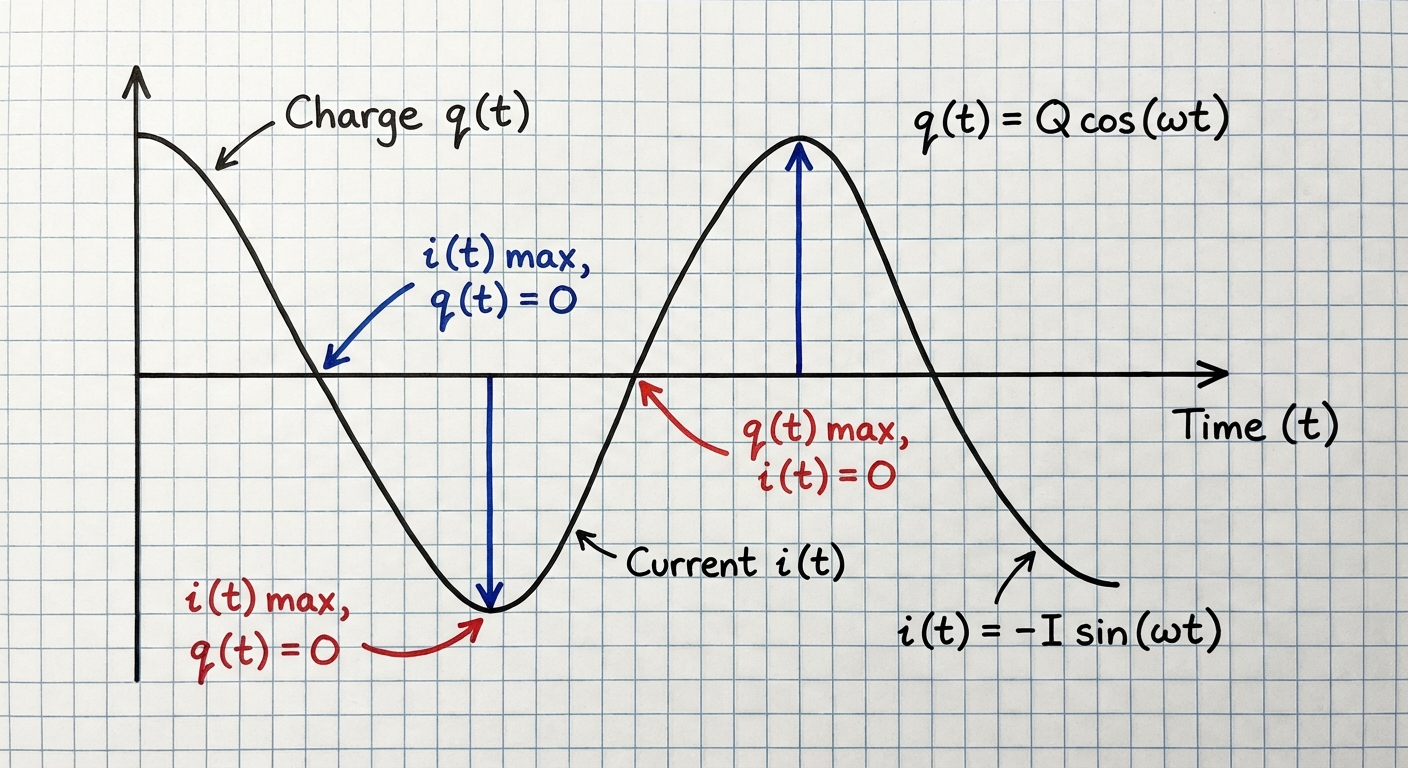
The solution to this differential equation is sinusoidal:
Taking the derivative gives the current:
Note: Current and Charge are $90^\circ$ ($\pi/2$ radians) out of phase.
Key Parameters
| Parameter | Formula | Definition |
|---|---|---|
| Angular Frequency | $\omega = \frac{1}{\sqrt{LC}}$ | The rate of oscillation in rad/s. |
| Frequency | $f = \frac{1}{2\pi\sqrt{LC}}$ | Cycles per second (Hz). |
| Period | $T = 2\pi\sqrt{LC}$ | Time for one full cycle. |
Conservation of Energy in LC Circuits
If resistance is zero, total energy is conserved. At any instant:
The Mechanical Analogy
It is crucial for the AP exam to understand the analogy between LC circuits and a Mass-Spring system:
| LC Circuit | Mass-Spring System |
|---|---|
| Inductance ($L$) | Mass ($m$) — Inertia/Resistance to change |
| Inverse Capacitance ($1/C$) | Spring Constant ($k$) — Stiffness |
| Charge ($q$) | Position ($x$) |
| Current ($i$) | Velocity ($v$) |
| Magnetic Energy ($\frac{1}{2}LI^2$) | Kinetic Energy ($\frac{1}{2}mv^2$) |
| Electric Energy ($\frac{1}{2} \frac{q^2}{C}$) | Potential Energy ($\frac{1}{2}kx^2$) |
Common Mistakes & Pitfalls
Sign Errors in Loop Rules:
- Mistake: Always treating voltage across the inductor as negative.
- Correction: The term $-L(di/dt)$ represents the back EMF. If current is decreasing (negative slope), this term becomes positive, representing the inductor pushing current forward.
Confusing $t=0$ and $t=\infty$:
- Mistake: Thinking the inductor acts like a wire at $t=0$.
- Correction: Remember: Inductors hate change. At $t=0$, nothing happens ($I=0$, Open Circuit). At $t=\infty$, no change is happening, so the inductor "relaxes" (Short Circuit).
LC Phase Relationship:
- Mistake: Assuming max current happens at max charge.
- Correction: They are opposites. When the capacitor is full (max $q$), the current is momentarily stopped ($i=0$) as it prepares to reverse direction.
Mixing up $\tau$ formulas:
- Mistake: Using $RC$ for inductive circuits or $L/R$ for capacitive circuits.
- Correction: $RC$ is for capacitors (smooth charge storage). $L/R$ is for inductors (smooth current flow). Note that larger $R$ in an LR circuit makes the current change faster (smaller $\tau$), whereas larger $R$ in an RC circuit makes charging slower.