AP Physics C: E&M — Unit 3: Electric Circuits
3.1 Current, Resistance, and Electromotive Force
Current and Motion of Charge
Electric Current ($I$) is defined not just as charge flow, but specifically as the rate at which charge passes through a given cross-sectional area. In AP Physics C, we use calculus to describe non-uniform currents.
- Macroscopic Definition: $I = \frac{\Delta Q}{\Delta t}$ (Average Current)
- Calculus Definition:
- Unit: Ampere (A), where $1 \text{ A} = 1 \text{ C/s}$.
- Direction: By convention, current flows in the direction positive charge would move (from high potential to low potential). Real charge carriers (electrons) move opposite to this conventional current.
Current Density and Drift Velocity
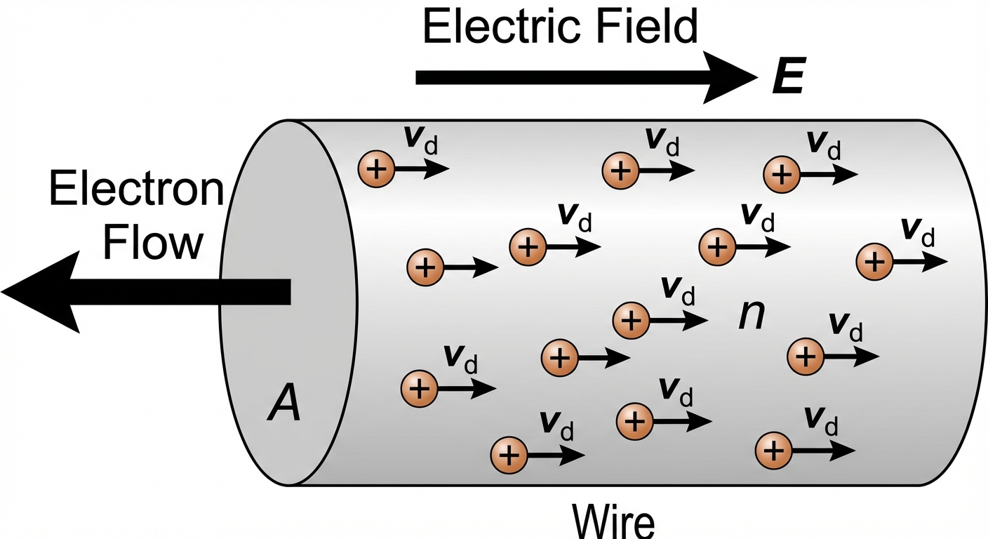
At a microscopic level, current depends on the properties of the charge carriers. Current Density ($J$) is the current per unit area.
- Formula:
- $n$: Charge carrier density (number of carriers per unit volume, $m^{-3}$)
- $q$: Charge of a single carrier (usually $e = 1.6 \times 10^{-19} \text{ C}$)
- $A$: Cross-sectional area of the wire
- $v_d$: Drift Velocity (the average slow velocity of electrons moving against the electric field due to collisions)
- Current Density Vector:
Resistance and Resistivity
Resistance ($R$) is the opposition to current flow. Resistivity ($\rho$) is an intrinsic property of the material itself, independent of its shape.
- Resistance Formula (Geometry):
- Longer wires ($L$) $\rightarrow$ Higher Resistance
- Thicker wires ($A$) $\rightarrow$ Lower Resistance
- Higher Resistivity ($\rho$) $\rightarrow$ Higher Resistance
- Temperature Dependence: Resistivity typically increases with temperature for metals.
- , where $\alpha$ is the temperature coefficient of resistivity.
Ohm's Law
Ohm's Law illustrates the relationship between Voltage, Current, and Resistance. Note that Ohm's law is an empirical model that applies to ohmic materials (linear resistors), not a fundamental law of nature like Conservation of Energy.
- Macroscopic Form:
- Microscopic Form:
- Here, $\sigma$ is conductivity, where $\sigma = 1/\rho$.
Electromotive Force (EMF) and Non-Ideal Batteries
A battery provides a potential difference called Electromotive Force ($\mathcal{E}$ or EMF). This is the work done per unit charge to move charge from low to high potential inside the source.
Real Batteries have internal resistance ($r$). Therefore, the Terminal Voltage ($V_{term}$) measured across the battery is not always equal to the EMF.
- Terminal Voltage Equation:
- If the battery is discharging (supplying current): $V_{term} < \mathcal{E}$
- If the battery is being charged (current forced backwards): $V_{term} > \mathcal{E}$
- If the switch is open (no current): $V_{term} = \mathcal{E}$
Power in Circuits
Electric Power ($P$) is the rate at which electrical potential energy is converted into other forms (heat, light, mechanical).
- General Formula:
- For Resistors (dissipated power):
3.2 DC Circuit Analysis
Kirchhoff's Rules
To solve complex circuits, we rely on two fundamental conservation laws.
Kirchhoff's Junction Rule (Conservation of Charge)
- The sum of currents entering any junction must equal the sum of currents leaving it.
Kirchhoff's Loop Rule (Conservation of Energy)
- The algebraic sum of potential differences (voltages) across all elements around any closed circuit loop must be zero.
- Sign Convention: Moving across a resistor in the direction of current is a voltage drop ($-IR$). Moving from the negative to positive terminal of a battery is a voltage gain ($+\mathcal{E}$).
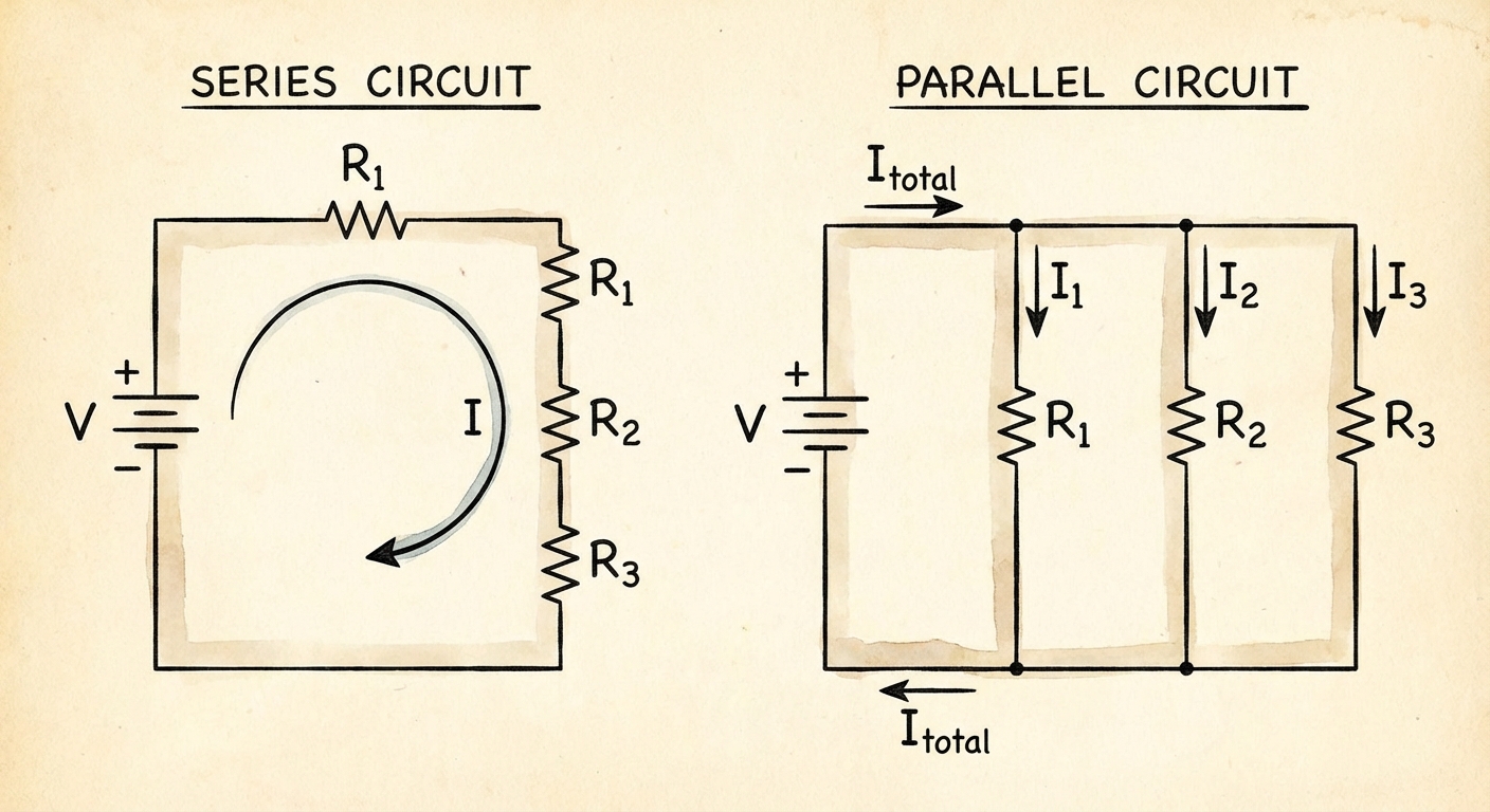
Resistors in Combinations
| Configuration | Voltage ($V$) | Current ($I$) | Equivalent Resistance ($R_{eq}$) |
|---|---|---|---|
| Series | Adds up ($V{eq} = V1 + V_2$) | Same everywhere ($I{eq} = I1 = I_2$) | |
| Parallel | Same everywhere ($V{eq} = V1 = V_2$) | Adds up ($I{eq} = I1 + I_2$) |
Circuit Instrumentation
Knowing how to measure circuits is a specific learning objective.
- Ammeter: Measures current. Must be placed in Series. Ideal resistance is 0 $\Omega$.
- Voltmeter: Measures potential difference. Must be placed in Parallel. Ideal resistance is Infinite ($\infty$) $\Omega$.
3.3 Capacitors in Circuits
Capacitors in Combinations
Capacitors follow the inverse rules of resistors regarding series and parallel equivalence.
| Configuration | Equivalent Capacitance ($C_{eq}$) | Logic |
|---|---|---|
| Series | Adding capacitors in series increases the effective gap distance, lowering capacitance. Total charge $Q$ is same for all. | |
| Parallel | Adding capacitors in parallel increases the effective plate area, increasing capacitance. Voltage $V$ is same for all. |
Energy in Capacitors
The potential energy ($UC$) stored in a capacitor is:
3.4 RC Circuits (Transient Behavior)
This is a critical topic for AP Physics C. It describes circuits containing both Resistors ($R$) and Capacitors ($C$) where the current varies with time. We examine two states: Charging and Discharging.
The Time Constant
The behavior of RC circuits is governed by the Time Constant ($\tau$). It represents the time scale of the circuit's response.
- Units: Seconds (Ohms $\times$ Farads = Seconds).
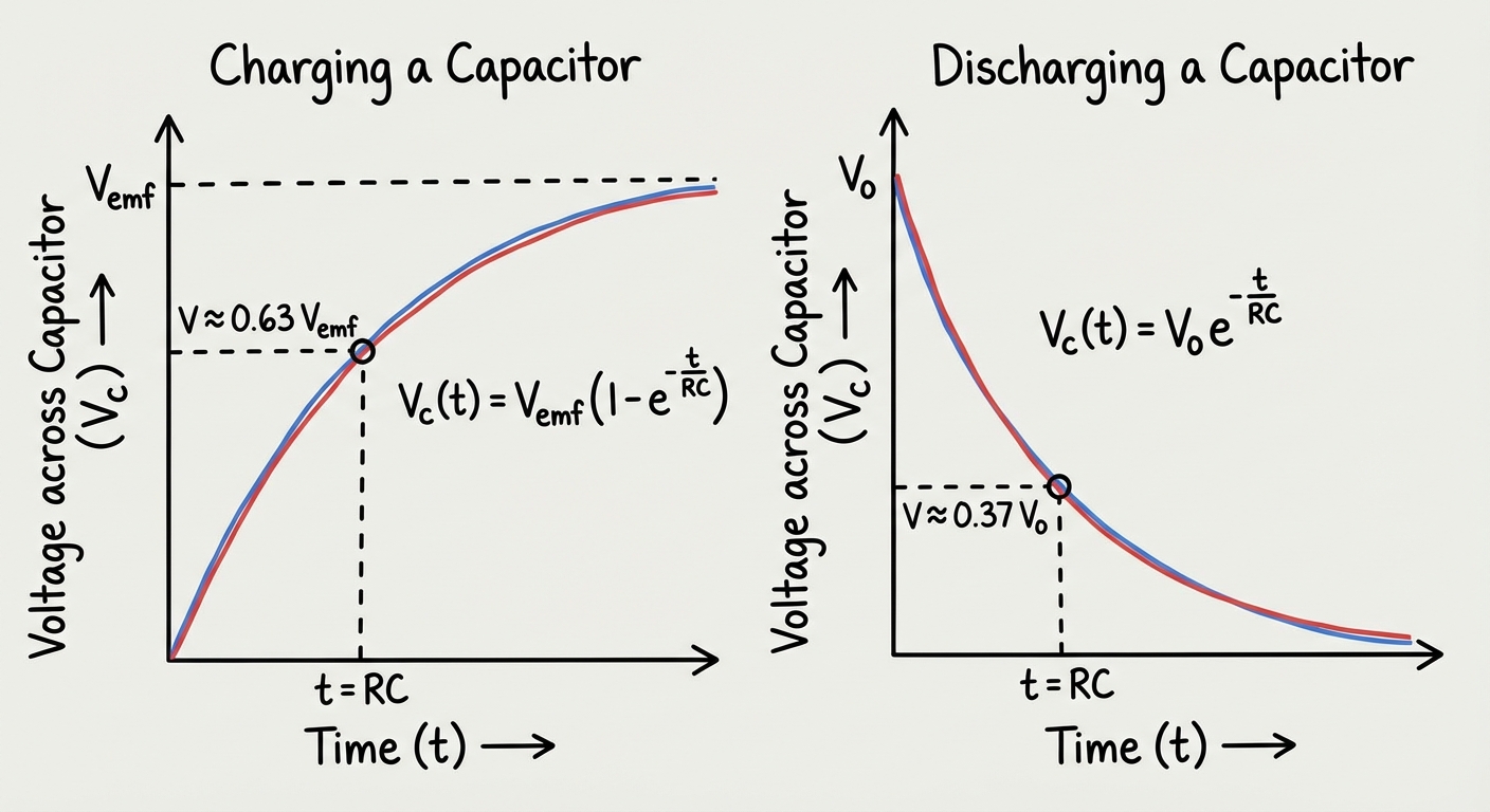
- At $t = \tau$, the function has changed by roughly $63\%$ of its total change.
Charging a Capacitor
Consider a circuit with a battery ($\mathcal{E}$), a resistor ($R$), and an uncharged capacitor ($C$) in series. When the switch closes at $t=0$:
- Initial State ($t=0$): Capacitor is empty ($Vc=0$). It acts like a short circuit (wire). Current is maximum: $I0 = \mathcal{E}/R$.
- Steady State ($t \rightarrow \infty$): Capacitor is full ($Q_{max} = C\mathcal{E}$). It acts like an open switch. Current is zero.
Derivation (Loop Rule):
Solving this differential equation yields the exponential functions:
- Charge:
- Current:
- Voltage across C:
Discharging a Capacitor
Consider a fully charged capacitor ($Q_0$) connected to a resistor ($R$) with no battery.
Derivation (Loop Rule):
Solving yields:
- Charge:
- Current: (Negative indicates flow direction reversed).
- Voltage across C:
Common Mistakes & Pitfalls
Confusing "Steady State" vs. "Transient" vs. "Initial":
- Initial ($t=0$): Uncharged C is a wire. Inductor (Unit 5) is a broken wire.
- Steady State ($t=\infty$): C is a broken wire (open circuit). Inductor is a wire.
- Don't apply steady-state logic ($I=0$ for capacitors) to questions asking about $t=0$.
Incorrect Ammeter/Voltmeter Hookup:
- Students often draw ammeters in parallel (which shorts the circuit) or voltmeters in series (which stops current flow). Remember: Ammeter = Wire (Series), Voltmeter = Infinite Resistor (Parallel).
Power vs. Energy:
- Power is a rate ($IV$ or $I^2R$). Energy is the accumulation of power over time ($Pt$ or $\int P dt$). Do not confuse Watts with Joules.
Misinterpreting Brightness:
- The brightness of a lightbulb is determined by its Power, not just current or voltage. Usually $P=I^2R$ is the safest metric to compare bulbs in series loops.
Local vs. Global Resistance:
- In solving $V=IR$, ensure $V$, $I$, and $R$ all refer to the same component or the same section of the circuit. Don't use the total battery voltage divided by a single resistor's resistance to find the total current (unless it's the only resistor).