Comprehensive Guide to Light Behavior and Thin Lenses
Refraction and Snell's Law
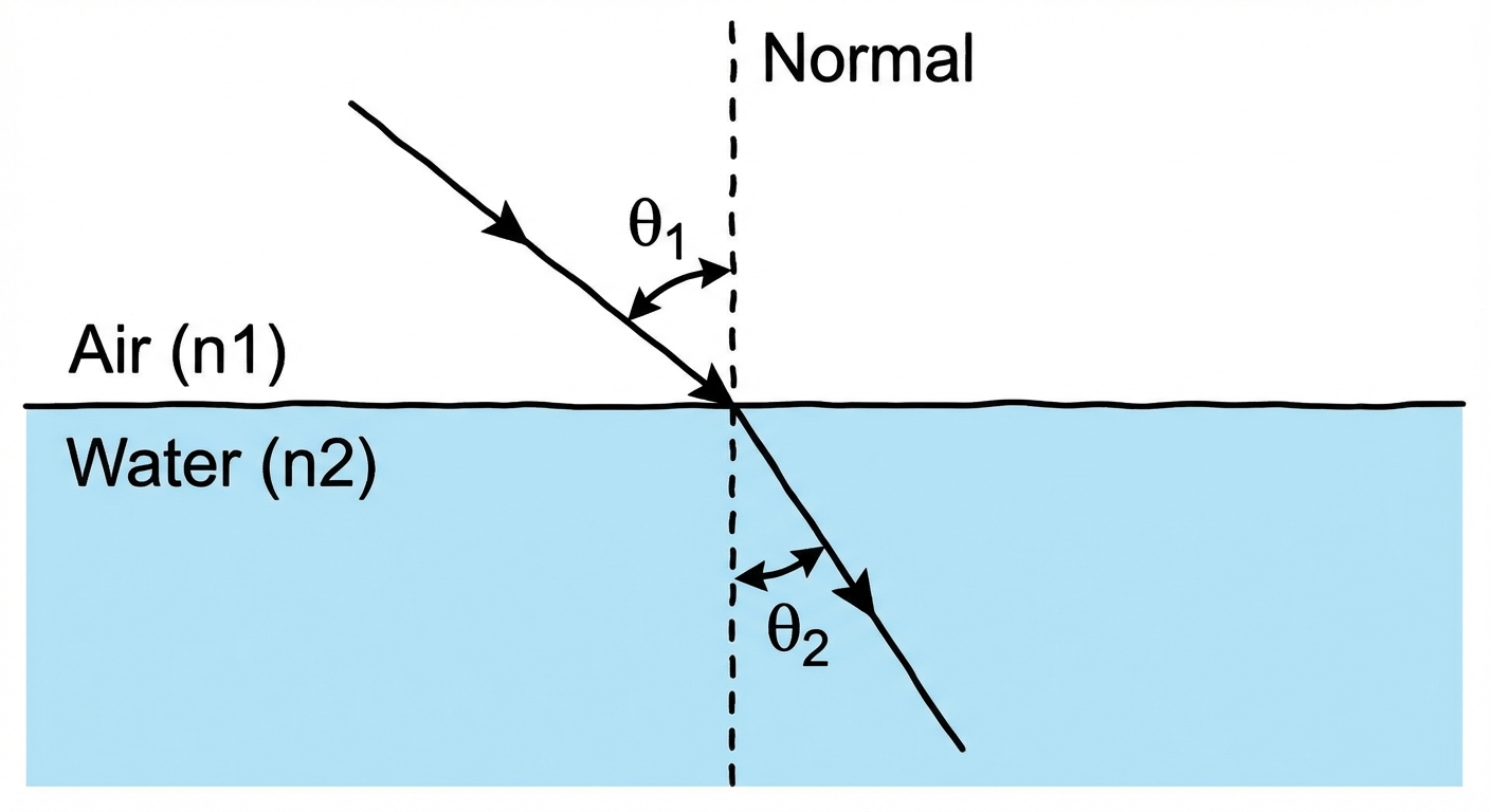
When light travels from one medium into another (e.g., from air to water), its speed changes. This change in speed causes the light ray to bend, a phenomenon known as Refraction. The amount of bending depends on the optical density of the materials, quantified by the Index of Refraction.
The Index of Refraction ($n$)
The index of refraction is a dimensionless ratio comparing the speed of light in a vacuum ($c$) to the speed of light in the medium ($v$).
- c: Speed of light in a vacuum ($\approx 3.00 \times 10^8 \text{ m/s}$)
- v: Speed of light in the medium
- Note: Since nothing travels faster than $c$, $n$ is always $\geq 1$ (e.g., $n{air} \approx 1.0$, $n{water} \approx 1.33$).
Wave Properties at Boundaries:
While speed ($v$) changes, the frequency ($f$) of the light wave remains constant. Because $v = \lambda f$, if the speed decreases, the wavelength ($\lambda$) must also decrease.
Snell's Law
Snell's Law relates the indices of refraction of the two media to the direction of propagation (the angles).
- $n1, n2$: Indices of refraction for the incident and refractive media.
- $\theta1, \theta2$: Angles of incidence and refraction.
Crucial Rule: Angles are always measured with respect to the Normal (a line perpendicular to the surface boundary), not the surface itself.
- Slow to Fast ($n1 > n2$): Light bends away from the normal.
- Fast to Slow ($n1 < n2$): Light bends toward the normal.
Example Calculation
A laser beam travels from air ($n = 1.0$) into lucite ($n = 1.5$) at an angle of incidence of $45^\circ$. Find the angle of refraction.
- Identify variables: $n1 = 1.0$, $\theta1 = 45^\circ$, $n2 = 1.5$, $\theta2 = ?$
- Apply Snell's Law:
- Solve:
Total Internal Reflection (TIR)
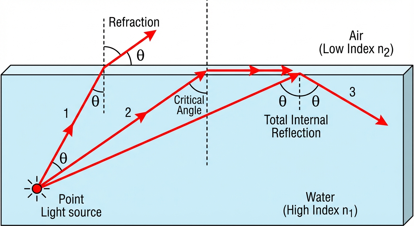
Total Internal Reflection occurs when a light ray hits a boundary but, instead of passing through, it reflects entirely back into the original medium. This phenomenon is the operating principle behind fiber optics.
Conditions for TIR
TIR is only possible under two specific conditions:
- The light is traveling from a medium with a higher index of refraction to a medium with a lower index ($n1 > n2$).
- The angle of incidence is greater than the Critical Angle ($\theta_c$).
The Critical Angle
The critical angle is the angle of incidence that results in an angle of refraction of exactly $90^\circ$ (traveling along the boundary). Using Snell's law where $\theta_2 = 90^\circ$:
Lenses and Image Formation
Lenses use refraction to converge or diverge light rays to form images. In AP Physics 2, we primarily deal with Thin Lenses.
| Lens Type | Shape | Optical Behavior | Focal Length ($f$) Sign |
|---|---|---|---|
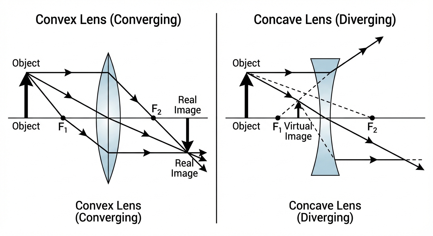
| Convex (Converging) | Thicker in center, thinner at edges | Converges parallel rays to a focal point | Positive ($+$) |
| Concave (Diverging) | Thinner in center, thicker at edges | Diverges parallel rays away from a focal point | Negative ($-$) |
Ray Tracing Rules
To locate an image geometrically, draw at least two of these effective rays from the tip of the object:
- Parallel Ray: Travels parallel to the principal axis, then refracts through the focal point ($F$).
- Focal Ray: Passes through the focal point ($F$), then refracts parallel to the principal axis.
- Central Ray: Passes through the geometric center of the lens and continues in a straight line (no deflection).
The Thin Lens Equation & Magnification
To find the exact position and size of an image, use the Thin Lens Equation and Magnification formula.
Thin Lens Equation:
Magnification ($M$):
Variable Definitions & Sign Conventions
Mastering sign conventions is the key to solving optics problems correctly.
| Variable | Meaning | Positive Sign ($+$) | Negative Sign ($-$) |
|---|---|---|---|
| $f$ | Focal Length | Converging Lens | Diverging Lens |
| $d_o$ | Object Distance | Real Object (in front of lens) | Virtual Object (rare in single lens systems) |
| $d_i$ | Image Distance | Real Image (formed on opposite side) | Virtual Image (formed on same side) |
| $M$ | Magnification | Upright Image | Inverted Image |
| $h_i$ | Image Height | Upright | Inverted |
Image Properties Cheat Sheet
- Real Images: Always inverted ($M < 0$), can be projected onto a screen, formed by converging lenses when $d_o > f$.
- Virtual Images: Always upright ($M > 0$), cannot be projected, formed by diverging lenses (always) or converging lenses when $d_o < f$ (magnifying glass).
Common Mistakes & Pitfalls
- The "Surface" Angle Trap: A very common error is using the angle between the light ray and the surface of the material. Always draw the Normal line and measure the angle between the Ray and the Normal.
- Frequency vs. Speed: Students often forget that while speed and wavelength change during refraction, Frequency does not change. The color of light depends on frequency, so light does not change color when entering glass/water.
- Sign Convention Errors:
- Forgetting that $d_i$ is negative for virtual images.
- Forgetting that $f$ is negative for diverging (concave) lenses.
- Degrees vs. Radians: Ensure your calculator is set to Degrees mode when calculating sines of angles.
- TIR Invalid Cases: Attempting to calculate a critical angle when light goes from Low-$n$ to High-$n$ (e.g., Air to Water). Your calculator will give an error because $\sin \theta$ cannot be $> 1$.