Unit 3: Direct Current (DC) Circuit Analysis
Fundamentals of DC Circuits
In Direct Current (DC) circuits, electric charge flows in only one direction. While simple circuits can be solved using Ohm’s Law alone, complex networks require a more robust set of conservation laws known as Kirchhoff's Rules. Understanding the behavior of potential difference (voltage), current, and resistance in these configurations is the backbone of AP Physics C: Electricity and Magnetism.
Kirchhoff's Rules
Gustav Kirchhoff extended Ohm's laws to complex circuit networks using two fundamental conservation principles. These rules are essential when a circuit cannot be simplified merely into series and parallel combinations (e.g., multi-loop circuits with multiple batteries).
1. The Junction Rule (Conservation of Charge)
Based on the principle that electric charge is neither created nor destroyed, the sum of currents entering any junction (node) must equal the sum of currents leaving it.
- Junction: A point where three or more wires meet.
- If you guess the direction of current wrong in a calculation, your final answer will simply be negative, indicating the current flows opposite to the direction you chose.
2. The Loop Rule (Conservation of Energy)
Based on the principle that the electrostatic force is conservative, the algebraic sum of changes in potential around any closed circuit loop must be zero. If you start a "hike" at one point in the circuit and return to the same point, your total elevation (potential) change is zero.
Sign Conventions for the Loop Rule
Using the Loop Rule correctly depends entirely on consistent sign conventions. Imagine tracing a path through the circuit components:
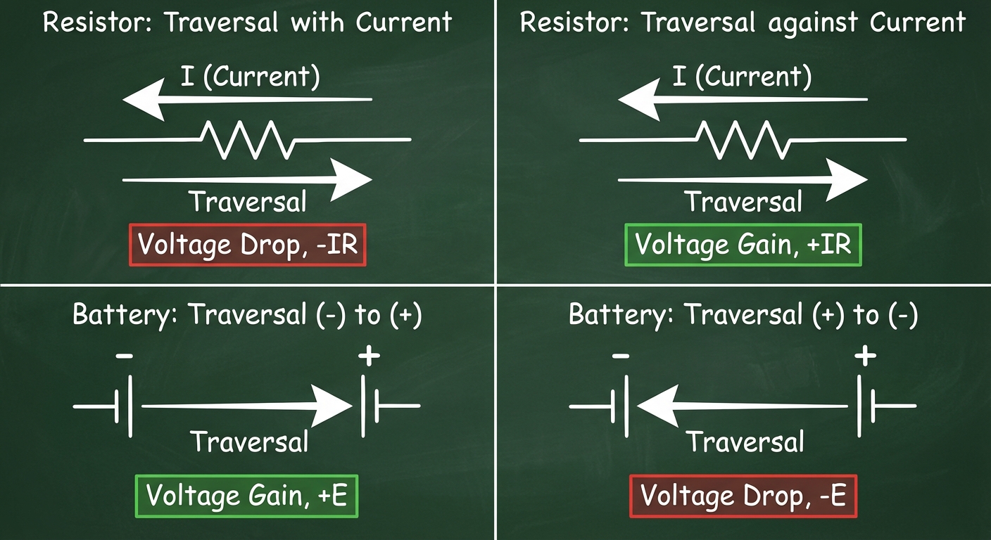
- Resistors:
- Traversing with the current direction: Electric potential drops ($-\Delta V = -IR$).
- Traversing against the current direction: Electric potential rises ($+\Delta V = +IR$).
- Batteries (EMF Sources):
- Traversing from negative to positive terminal: Potential rises ($+\mathcal{E}$).
- Traversing from positive to negative terminal: Potential drops ($-\mathcal{E}$).
Resistors in Series and Parallel
Most complex circuits are combinations of two primary arrangements: series and parallel. Simplifying these into an Equivalent Resistance ($R_{eq}$) is often the first step in analysis.
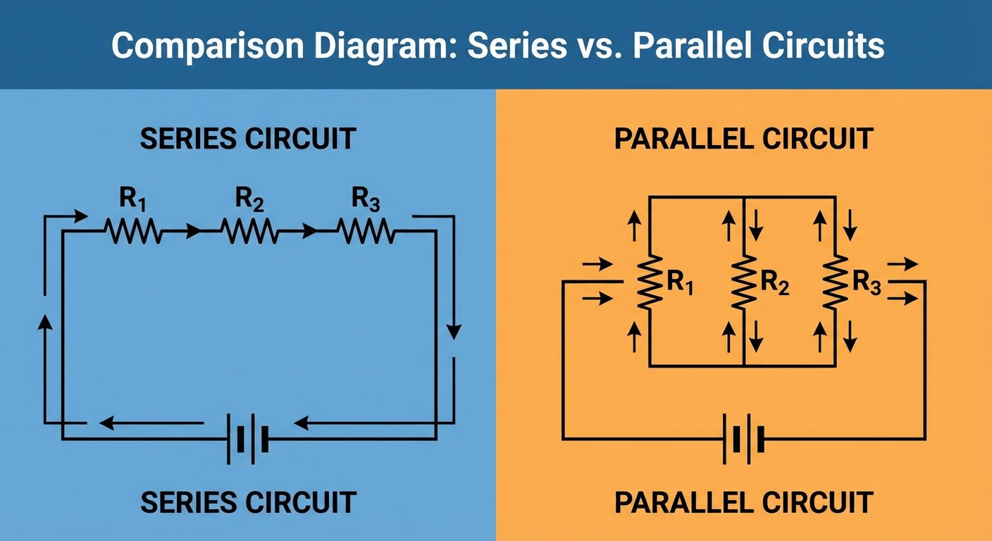
Resistors in Series
Components are arranged in a single continuous path.
- Current: The same current flows through every resistor ($I{total} = I1 = I_2 = \dots$).
- Voltage: The total voltage is the sum of the potential drops across each resistor ($V{total} = V1 + V_2 + \dots$).
Equivalent Resistance Example:
Note: Adding resistors in series increases the total resistance of the circuit. The equivalent resistance is always greater than the largest individual resistor.
Resistors in Parallel
Components are arranged in branched paths connecting the same two nodes.
- Voltage: The potential difference across each branch is identical ($V{total} = V1 = V_2 = \dots$).
- Current: The total current splits among the branches ($I{total} = I1 + I_2 + \dots$).
Equivalent Resistance Formula:
Note: Adding resistors in parallel decreases the total resistance. The equivalent resistance is always smaller than the smallest individual resistor.
Mnemonics for Properties
- Series: "Same Stream" (Current is essential like water in a stream; it assumes the path of the stream).
- Parallel: "Same Drop" (Every branch drops from the same high potential cliff to the same low potential valley).
Power in Circuits
Electric Power is the rate at which electrical energy is converted into other forms, such as thermal energy (heat in a resistor), light, or mechanical work.
General Formulas
The fundamental definition of electrical power is:
By substituting Ohm's Law ($V = IR$), we get two alternative forms useful for resistors:
- In terms of Current: $P = I^2 R$ (Useful for Series circuits where $I$ is constant).
- In terms of Voltage: $P = \frac{(\Delta V)^2}{R}$ (Useful for Parallel circuits where $V$ is constant).
Real Batteries and Internal Resistance
In the real world, batteries are not ideal. They have an Internal Resistance ($r$).
- EMF ($\mathcal{E}$): The ideal voltage the battery generates chemically.
- Terminal Voltage ($V_T$): The actual voltage measured across the battery terminals when current flows.
This means the power delivered to the external circuit is less than the total power generated by the EMF:
- Total Power Generated: $P_{gen} = I \mathcal{E}$
- Power Dissipated inside Battery: $P_{internal} = I^2 r$
- Power Delivered to Load: $P{load} = IVT$
Worked Example: Multi-Loop Circuit
Problem: Consider a circuit loop with two batteries opposing each other.
- Battery 1: $\mathcal{E}_1 = 20V$
- Battery 2: $\mathcal{E}_2 = 5V$
- Resistor: $R = 3\Omega$
- Internal resistances are negligible.
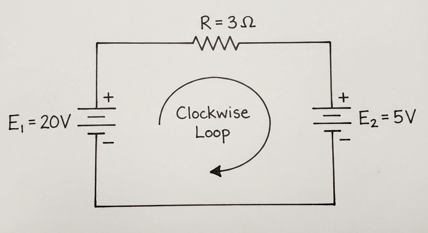
Step 1: Assign Current Direction.
Let's guess the current $I$ flows clockwise (out of the larger battery $\mathcal{E}_1$).
Step 2: Apply Loop Rule.
Start at the bottom left and move clockwise.
- Go through $\mathcal{E}_1$ ($-$ to $+$): Gain $+20V$
- Go through $R$ (with current): Drop $-I(3\Omega)$
- Go through $\mathcal{E}_2$ ($+$ to $-$): Drop $-5V$
- Return to start $= 0$
Step 3: Solve.
Since $I$ is positive, our clockwise assumption was correct.
Step 4: Calculate Power.
- Power supplied by $\mathcal{E}_1$: $P = IV = (5A)(20V) = 100W$
- Power consumed by $\mathcal{E}_2$ (charging): $P = IV = (5A)(5V) = 25W$
- Power dissipated by Resistor: $P = I^2R = (5^2)(3) = 75W$
- Check: Supply (100W) = Consumed (25W + 75W). Energy is conserved.
Common Mistakes & Pitfalls
Sign Errors in Loop Rule: This is the #1 mistake. Students often forget that traversing a resistor against the current is a voltage gain, or that traversing a battery from $+$ to $-$ is a voltage drop.
- Fix: Draw loop arrows physically on your paper before writing the equation.
Confusing Equivalent Resistance Math:
- For parallel resistors, students often calculate $\sum \frac{1}{Ri}$ and forget to flip the fraction at the end to find $R{eq}$.
- Fix: Always check if your Parallel $R_{eq}$ is smaller than the smallest branch resistor. If it's bigger, you forgot to flip.
Misapplying Power Formulas:
- Using $P = V^2/R$ for a resistor in a series circuit but using the total battery voltage rather than the specific voltage drop across that resistor.
- Fix: Only use values specific to the component you are analyzing.
Ignoring Internal Resistance:
- Assuming the terminal voltage is always equal to the EMF.
- Fix: Remember $V{term} < \mathcal{E}$ when the battery is discharging, and $V{term} > \mathcal{E}$ if the battery is being charged.