Comprehensive Guide to Electromagnetic Induction
Magnetic Flux: The Measure of "Flow"
Before understanding how electricity is created from magnetism, you must understand the quantity that relates the magnetic field to physical space: Magnetic Flux. Think of magnetic flux as the number of magnetic field lines passing through a specific surface area. It is the precursor to understanding how changing magnetic environments create voltage.
Definition and Calculation
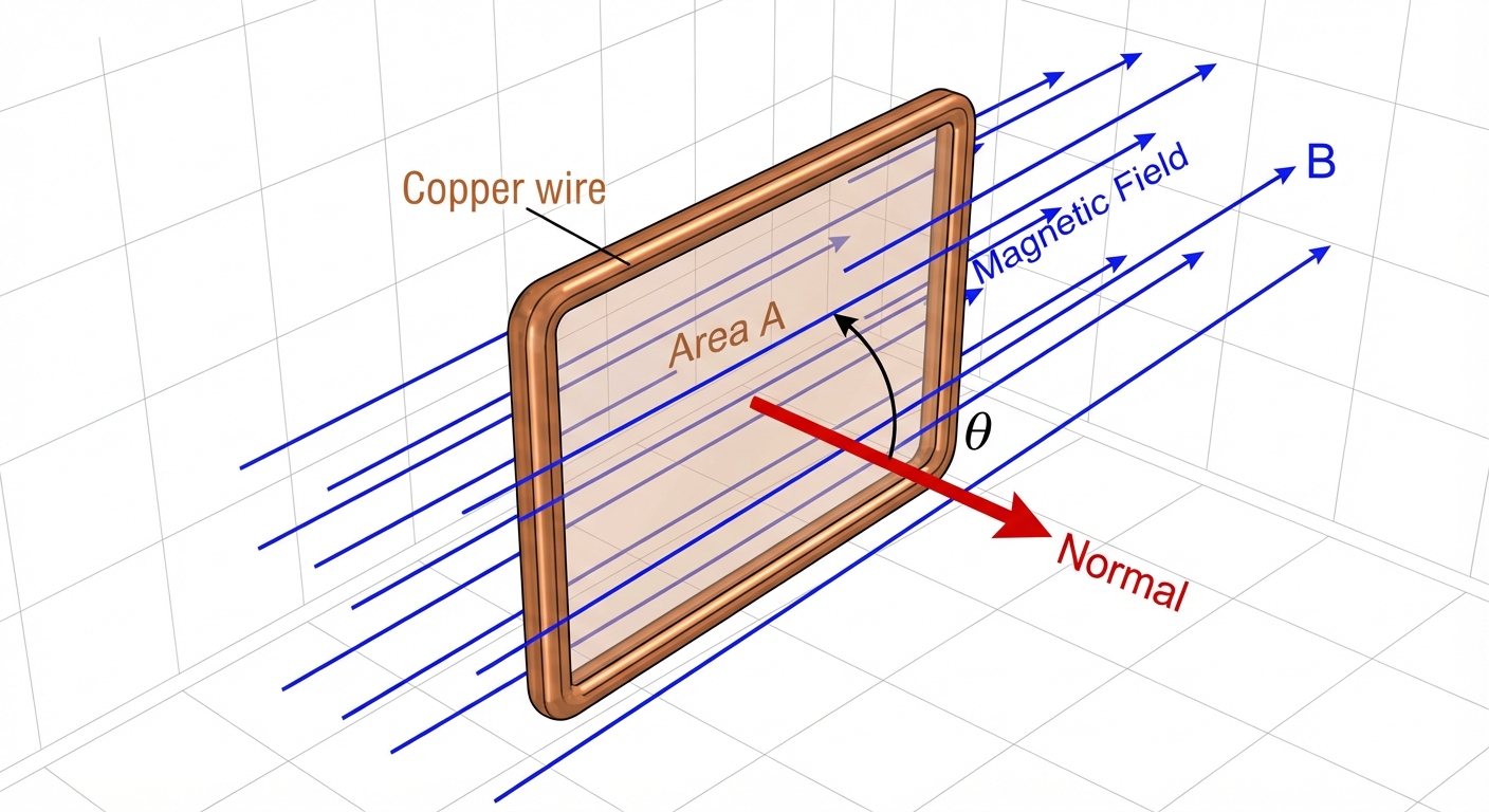
Magnetic Flux (denoted as $\Phi_B$) is defined as the scalar product of the magnetic field vector and the area vector. The area vector is always perpendicular (normal) to the surface.
Where:
- $\Phi_B$ is the magnetic flux measured in Webers (Wb) (which is equivalent to $T \cdot m^2$).
- $B$ is the magnitude of the magnetic field (Tesla).
- $A$ is the area of the surface ($m^2$).
- $\theta$ is the angle between the magnetic field lines and the normal line (the line perpendicular to the surface).
conceptualizing the Angle $\theta$
This angle is the source of the most common errors in AP Physics 2 flux problems.
| Orientation | Angle $\theta$ (field vs. normal) | Value of $\cos(\theta)$ | Flux $\Phi_B$ |
|---|---|---|---|
| Field is perpendicular to the surface | $0^\circ$ | $1$ | Maximum ($BA$) |
| Field is parallel to the surface | $90^\circ$ | $0$ | Zero ($0$) |
| Field enters at an angle | $\theta$ | $\cos(\theta)$ | $BA\cos(\theta)$ |
Faraday's Law and Lenz's Law
In the early 19th century, Michael Faraday discovered that a constant magnetic field does nothing to a stationary wire loop. However, a changing magnetic flux induces an electromotive force (emf).
Faraday's Law of Induction
Faraday's Law states that the magnitude of the induced emf ($\mathcal{E}$) in a conducting loop is equal to the rate of change of magnetic flux through the loop.
\mathcal{E} = -\frac{\Delta \PhiB}{\Delta t} = -\frac{\Phif -
\Phi_i}{\Delta t}
If you have a coil with $N$ loops (turns) of wire, the effect is multiplied:
Where:
- $\mathcal{E}$ is the induced emf (Volts).
- $N$ is the number of loops.
- $\frac{\Delta \Phi_B}{\Delta t}$ is the rate of change of flux (Webers/second).
Ways to Change Flux
Since $\Phi_B = BA\cos(\theta)$, you can induce an emf by changing any of these three variables over time:
- Change $B$: Move a magnet closer or further away, or vary the current in a solenoid creates the field.
- Change $A$: Stretch or compress a flexible loop, or move a rectangular loop into/out of a magnetic field region.
- Change $\theta$: Rotate the loop within the magnetic field (this is how generators work).
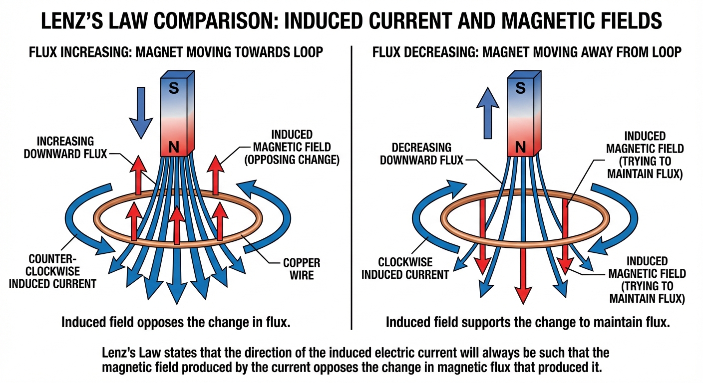
Lenz's Law: The Conservation of Energy
You likely noticed the negative sign ($ - $) in Faraday's equation. This represents Lenz's Law, which predicts the direction of the induced current.
Definition: The direction of the induced current is such that the magnetic field created by the induced current opposes the change in the original magnetic flux.
Nature hates change. If flux is increasing, the loop tries to decrease it. If flux is decreasing, the loop tries to increase/maintain it.
4-Step Process to Determine Current Direction
- Determine the direction of the external magnetic field ($B_{ext}$).
- Determine if the flux is increasing or decreasing.
- Determine the direction of the Induced Field ($B_{ind}$):
- If Flux is increasing: $B{ind}$ points opposite to $B{ext}$.
- If Flux is decreasing: $B{ind}$ points in the same direction as $B{ext}$.
- Use the Right-Hand Rule:
- Point your right thumb in the direction of the required $B_{ind}$.
- Your fingers curl in the direction of the induced current.
Motional EMF
A special case of induction occurs when a conductor moves through a magnetic field. The most common example is a conducting bar sliding along two parallel rails connected by a resistor.
As the bar moves, the area of the loop changes ($A = \ell \cdot x$), changing the flux.
Where:
- $B$ is the magnetic field strength (perpendicular to motion).
- $\ell$ is the length of the bar moving in the field.
- $v$ is the velocity of the bar.
Note: For current to flow, the circuit must be closed. If just a single metal rod moves through space, an emf (potential difference) is induced between its ends, but no current flows unless it is part of a complete circuit.
Applications of Electromagnetic Induction
Electric Generators
An electric generator converts mechanical energy into electrical energy. It consists of a coil of wire rotating in a magnetic field.
- As the coil rotates, the angle $\theta$ changes continuously.
- The flux varies as a cosine function: $\Phi = BA\cos(\omega t)$.
- The induced emf acts as a sine function, creating Alternating Current (AC).
Transformers
Transformers are used to change the voltage of an alternating current. They consist of two coils (primary and secondary) wrapped around an iron core. They rely entirely on changing flux—transformers do not work with DC.
Key Formulas:
Relation of Voltage and Turns (The Transformer Equation):
Conservation of Energy (Ideal Transformer):
Assuming 100% efficiency, Power In = Power Out.
Therefore, we can combine them:
| Type | Turns Ratio | Voltage Change | Current Change |
|---|---|---|---|
| Step-Up | $Ns > Np$ | Increases ($Vs > Vp$) | Decreases ($Is < Ip$) |
| Step-Down | $Ns < Np$ | Decreases ($Vs < Vp$) | Increases ($Is > Ip$) |
Common Mistakes & Pitfalls
1. The Normal Line Confusion
Mistake: Students often use the angle given in the problem without checking if it is relative to the surface or the normal line.
Correction: The formula $\Phi = BA\cos\theta$ requires $\theta$ to be the angle between the B-field and the Normal vector. If the problem gives the angle between the field and the plane/surface, use $90^\circ - \text{given angle}$.
2. "Flux vs. Change in Flux"
Mistake: Thinking that a high magnetic flux produces a high emf.
Correction: Induction relies on the rate of change. A massive, super-strong magnetic field produces zero emf if it is constant/stationary. A small field changing very rapidly produces a large emf.
3. Current Direction Logic
Mistake: Thinking the induced field ($B{ind}$) always points opposite to the external field ($B{ext}$).
Correction: This is only true if flux is increasing. If flux is decreasing, the induced field tries to prop it up and points in the same direction as the external field.
4. Transformers and DC
Mistake: trying to solve transformer problems where a DC battery is connected to the primary coil.
Correction: DC current is constant. Constant current creates a constant B-field. Constant B-field means $\Delta \Phi = 0$. Therefore, Output Voltage is 0.