Mastering Electric Circuit Analysis: DC Circuits
Fundamentals of DC Circuit Topology
In AP Physics 2, circuit analysis revolves around Direct Current (DC) circuits in a steady state. Before diving into math, it is crucial to understand the topology—how components are arranged. This arrangement dictates how conservation laws (Energy and Charge) apply to voltage and current.
Series Circuits
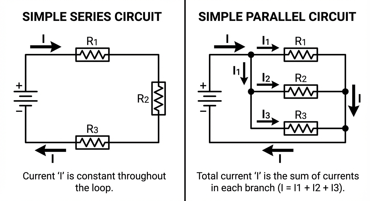
In a Series Circuit, components are arranged in a single continuous loop. There is only one path for the charge carriers (electrons) to flow.
Key Characteristics:
- Current ($I$): Because charge cannot be created or destroyed and there is nowhere else to go, the current is the same through every component.
- Voltage ($\Delta V$): The total potential difference (provided by the battery/EMF) is shared among the components. The sum of voltage drops equals the source voltage.
- Equivalent Resistance ($R{eq}$): Resistors in series add directly. Adding more resistors in series increases the total resistance.
Parallel Circuits
In a Parallel Circuit, components are arranged on separate branches. The current splits at a junction (node), travels through different paths, and recombines.
Key Characteristics:
- Voltage ($\Delta V$): Each branch is directly connected across the same two points (usually the battery terminals), so the potential difference across each parallel component is the same.
- Current ($I$): The total current flowing from the source is the sum of the currents in individual branches. (Think of water pipes splitting into smaller pipes).
- Equivalent Resistance ($R{eq}$): Resistors in parallel add reciprocally. Adding more resistors in parallel decreases the total resistance because you are providing more pathways for flow.
| Feature | Series Circuits | Parallel Circuits |
|---|---|---|
| Current | Same everywhere | Splits among branches |
| Voltage | Splits among components | Same across branches |
| Resistance | $R_{eq} >$ any individual $R$ | $R_{eq} <$ smallest individual $R$ |
| Bulb Behavior | If one burns out, all go out | If one burns out, others stay lit |
Kirchhoff's Rules
When circuits become too complex to analyze using simple series/parallel reduction, we use Gustav Kirchhoff’s rules. These are essentially statements of conservation laws.
1. The Junction Rule (Conservation of Charge)
Because electric charge is conserved, the amount of charge flowing into any specific point (junction) in a circuit must equal the amount of charge flowing out.
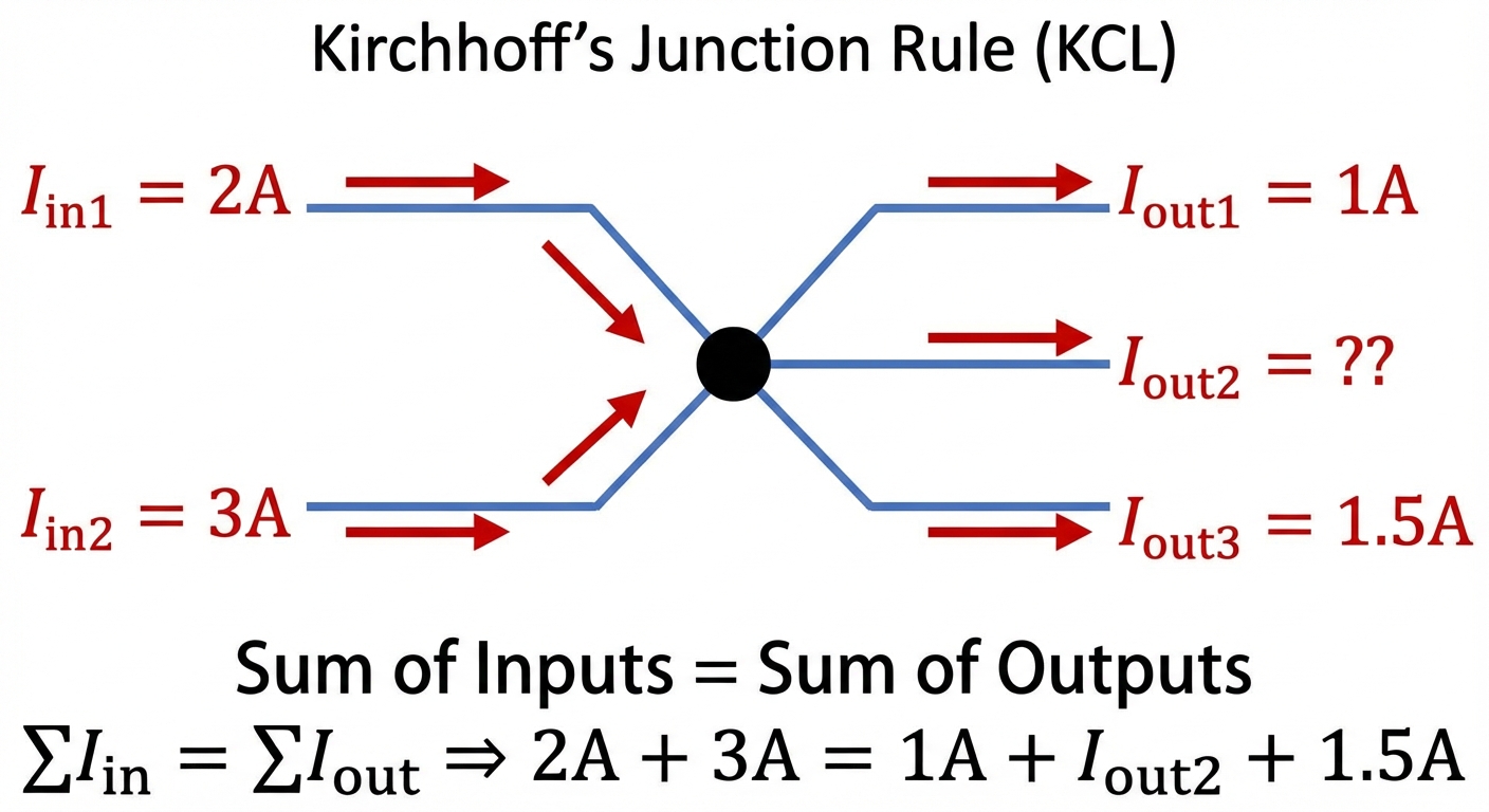
Example: If 5A flows into a junction splits into two wires, and one wire carries 2A, the other must carry 3A.
2. The Loop Rule (Conservation of Energy)
This rule states that the sum of changes in potential (voltage) around any closed loop must identify zero. This is a restatement of the Conservation of Energy—a charge that moves around a loop and returns to the start must have the same potential energy it started with.
To use this, imagine walking around a loop in the circuit. You must apply consistent Sign Conventions:
- Batteries: Traversing from negative (-) to positive (+) terminal: $+ \varepsilon$ (Gain). Traversing from positive (+) to negative (-): $- \varepsilon$ (Drop).
- Resistors: Traversing with the expected direction of current: $-IR$ (Energy is dissipated/lost). Traversing against the direction of current: $+IR$ (Mathematically climbing back up the potential).
Analyzing Combination Circuits
Most AP Physics 2 problems involve Combination Circuits, which contain both series and parallel segments. The standard strategy is the "Simplify and Rebuild" method.
Worked Example
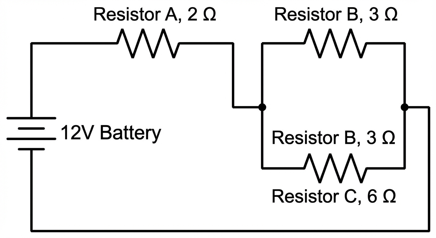
Scenario: A 12V battery is connected to a circuit. Resistor A ($2\Omega$) is in series with a parallel combination of Resistor B ($3\Omega$) and Resistor C ($6\Omega$). Find the current through Resistor C.
Step 1: Simplify the Parallel Block
First, find the equivalent resistance of the parallel block ($RB$ and $RC$).
Step 2: Find Total Equivalent Resistance
Now, the circuit looks like Resistor A ($2\Omega$) in series with the equivalent block $Rp$ ($2\Omega$).
Step 3: Find Total Current
Use Ohm's Law ($I = \Delta V / R$) for the whole circuit.
Step 4: Work Backwards to Components
Since Resistor A is in series with the battery, it gets the full total current ($3A$).
- Voltage drop across A: $\Delta VA = I{total} \cdot R_A = 3A \cdot 2\Omega = 6V$.
Now, apply the Loop Rule. The battery provides 12V, and Resistor A consumes 6V. The remaining voltage applies to the parallel block:
Because they are in parallel, both Resistor B and Resistor C have a $6V$ drop across them.
Step 5: Solve for Specific Current
Calculate current through Resistor C ($6\Omega$) using its specific voltage ($6V$).
(Self Check: $IB = 6V/3\Omega = 2A$. Total current $IB + I_C = 2A + 1A = 3A$. Matches our total. Success!)
Common Mistakes & Pitfalls
"Current gets used up":
- Misconception: Students often think current decreases after passing through a resistor.
- Correction: Current is the rate of flow of charge. Charge is conserved. Current entering a resistor equals current leaving it. What gets "used up" (converted) is Electrical Potential Energy (Voltage).
Confusing Equivalent Resistance Logic:
- Misconception: Thinking that adding a resistor always increases total resistance.
- Correction: This is true for logical series connections only. Adding a resistor in parallel opens a new path, effectively widening the "pipe," which decreases total resistance.
Local vs. Global Ohm's Law:
- Trap: Using the total voltage ($V{battery}$) with a single resistor's resistance ($R1$) to find that resistor's current.
- Correction: Only use $I = V/R$ for matched sets. $I{total} = V{total} / R{total}$. Or $I1 = V1 / R{1}$. Never mix "total" values with "component" values.
Kirchhoff Loop Sign Errors:
- Trap: Always subtracting $IR$ or adding $\varepsilon$ regardless of loop direction.
- Correction: Always draw your loop direction arrow. If you walk against the current arrow you drew, voltage goes UP ($+IR$).
Mnemonic for Capacitors vs Resistors
- Resistors: Series adds up (ReSeries = Sum). Parallel is inverse.
- Capacitors (Unit 3 later topics): The exact Opposite. Capacitors in Series add inversely; Capacitors in Parallel add up. Remember: "Capacitors are Contrary."