Comprehensive Guide to Electromagnetism and Maxwell's Equations
Unit 5: Electromagnetism
5.1 Magnetic Flux and Electromagnetic Induction
Magnetic Flux ($\Phi_B$)
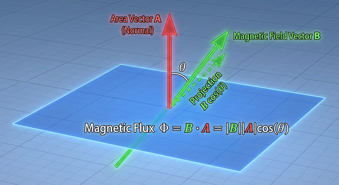
Magnetic Flux quantifies the amount of magnetic field passing through a specific area. It is conceptually similar to airflow through a window; it depends on the strength of the field, the size of the area, and the angle of the area relative to the field.
- Definition: The surface integral of the magnetic field $\mathbf{B}$ over an area $\mathbf{A}$.
- Formula (General):
- For Uniform Field and Flat Area:
- Where $\theta$ is the angle between the magnetic field lines and the area vector (normal to the surface).
- Unit: Weber ($Wb$), where $1 \, Wb = 1 \, T \cdot m^2$.
Faraday’s Law of Induction
Discovered by Michael Faraday, this fundamental law connects a changing magnetic environment to electric fields.
- The Law: The magnitude of the induced electromotive force (EMF) in a conducting loop is equal to the rate of change of magnetic flux through the loop.
- Formula:
- $\mathcal{E}$ = Induced EMF (Volts)
- $N$ = Number of turns (loops) in the coil
- $\frac{d\Phi_B}{dt}$ = Rate of change of magnetic flux ($Wb/s$)
Ways to induce EMF (change $\Phi_B$):
- Change the magnetic field strength ($B$).
- Change the area of the loop within the field ($A$).
- Change the orientation/angle of the loop ($cos\theta$).
Lenz’s Law
Lenz's Law explains the negative sign in Faraday's Law. It is a manifestation of the Conservation of Energy.
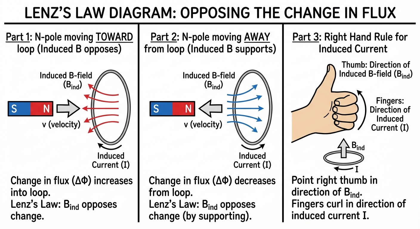
- Definition: The direction of the induced current is such that the magnetic field it creates opposes the change in magnetic flux that produced it.
- Process for determining direction:
- Determine the direction of the original magnetic field ($B_{orig}$).
- Determine if the flux is increasing or decreasing.
- If flux is increasing, the induced field ($B{ind}$) points opposite to $B{orig}$.
- If flux is decreasing, the induced field ($B{ind}$) points in the same direction as $B{orig}$ (to try to maintain the status quo).
- Use the Right-Hand Rule (thumb points in $B_{ind}$, fingers curl in current direction) to find the current vector.
Motional EMF
When a conductor moves through a magnetic field, magnetic forces on the charge carriers cause charge separation, creating a potential difference.
- Scenario: A conducting bar of length $\ell$ moving with velocity $v$ perpendicular to a uniform magnetic field $B$.
- Formula:
- Mechanism: The magnetic force ($FB = qvB$) pushes electrons to one end of the bar until the electric force ($FE = qE$) balances it.
5.2 Inductance and Inductors
Self-Inductance
Inductance is the property of a conductor to oppose changes in the current flowing through it. A changing current creates a changing magnetic flux through the circuit's own loop, inducing a "back EMF."
- Definition of Inductance ($L$):
- Induced EMF in an Inductor:
- Unit: Henry ($H$), where $1 \, H = 1 \, V \cdot s / A$.
Inductance of a Solenoid
For a long solenoid (ideal inductor):
- $\mu_0$ = Permeability of free space ($4\pi \times 10^{-7} \, T\cdot m/A$)
- $N$ = Total turns
- $n$ = Turns per unit length ($N/\ell$)
- $A$ = Cross-sectional area
- $\ell$ = Length of solenoid
- Note: Inductance depends only on geometry, not on the current or voltage.
Energy Stored in a Magnetic Field
Just as capacitors store energy in an electric field, inductors store energy in a magnetic field.
- Formula:
- Energy Density (Energy per unit volume in a B-field):
5.3 RL Circuits (Transient Behavior)
An RL circuit contains a resistor and an inductor in series with a voltage source. The inductor prevents the current from changing instantaneously.
Charging Phase (Switch Closed)
When a battery with EMF $\mathcal{E}$ is connected:
- At $t=0$: Inductor acts as an open circuit (infinite resistance to change). $I_0 = 0$.
- At $t=\infty$: Inductor acts as a short circuit (wire). $I_{max} = \mathcal{E}/R$.
Derivation via Kirchhoff's Voltage Law (KVL):
Solving this differential equation yields:
- Time Constant ($\tau$): The time it takes for the current to reach $\approx 63\%$ of its max value.
- Voltage across Inductor:
Discharging Phase (Source Removed)
When the battery is removed and the loop is closed:
- The inductor acts as a temporary source, keeping current flowing in the original direction, decaying exponentially.
- Current Formula:
5.4 LC Circuits (Electromagnetic Oscillations)
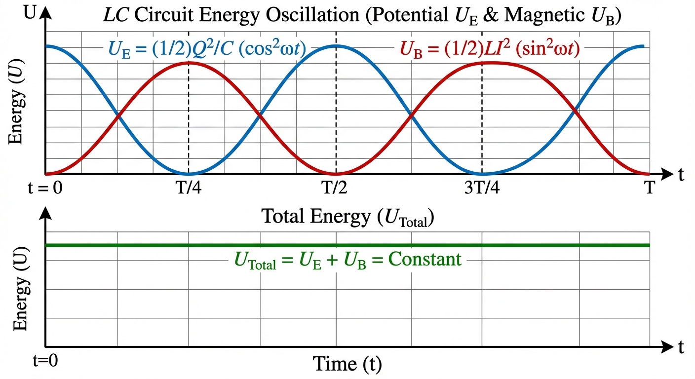
An LC circuit (Inductor and Capacitor with no resistance) exhibits Simple Harmonic Motion (SHM) where energy produces oscillations between the electric field of the capacitor and the magnetic field of the inductor.
The Oscillation Cycle
- Max Charge: Energy is purely electric ($U_E = Q^2/2C$); Current $I=0$.
- Discharging: Capacitor drives current through inductor. $UE$ converts to $UB$.
- Max Current: Capacitor empty ($Q=0$); Energy is purely magnetic ($U_B = 1/2 LI^2$).
- Recharging: Inductor forces current to continue recharging the capacitor with opposite polarity.
Mathematical Analysis
Using KVL ($VL + VC = 0$):
Since $I = +\frac{dQ}{dt}$ (definitions vary by sign convention, but result is SHM):
This is the differential equation for SHM ($x'' + \omega^2 x = 0$).
- Angular Frequency:
- Charge as function of time:
- Current as function of time:
5.5 Maxwell’s Equations
Maxwell unified electricity and magnetism into four equations. In AP Physics C, you must understand the integral forms and their physical meanings.
| Name | Integral Equation | Physical Meaning |
|---|---|---|
| 1. Gauss’s Law (E) | $\oint \mathbf{E} \cdot d\mathbf{A} = \frac{Q{in}}{\epsilon0}$ | Electric flux relates to enclosed charge. Monopoles (charges) exist. |
| 2. Gauss’s Law (B) | $\oint \mathbf{B} \cdot d\mathbf{A} = 0$ | Net magnetic flux through a closed surface is zero. No magnetic monopoles exist; lines are continuous loops. |
| 3. Faraday’s Law | $\oint \mathbf{E} \cdot d\boldsymbol{\ell} = -\frac{d\Phi_B}{dt}$ | A changing magnetic flux induces a circulating electric field (EMF). |
| 4. Ampere-Maxwell Law | $\oint \mathbf{B} \cdot d\boldsymbol{\ell} = \mu0 I + \mu0 \epsilon0 \frac{d\PhiE}{dt}$ | Magnetic fields are created by conduction current ($I$) OR by changing electric flux (Displacement Current). |
Displacement Current
The term $\epsilon0 \frac{d\PhiE}{dt}$ is known as Displacement Current ($I_d$). It explains how magnetic fields exist between capacitor plates where no physical charge flows.
Common Mistakes & Pitfalls
- Flux Angle Confusion: Students often use the angle between the surface plane and the field. The formula requires the angle between the surface normal vector and the field. If B is parallel to the surface, $\theta=90^{\circ}$ and Flux is 0.
- Lenz's Law Direction: Do not confuse the flux direction with the change in flux direction. If flux is pointing North but decreasing, the change acts South, so the induced field acts North to compensate.
- Inductor Behavior: Remember: Inductors resist changes in current, not the current itself. A steady DC current flows through an ideal inductor with zero voltage drop ($V=L \cdot 0 = 0$).
- Motional EMF Integral: When deriving EMF using $\int (v \times B) \cdot dl$, ensure you account for the direction of integration. Usually, the magnitude $Blv$ is sufficient, but direction comes from the Right-Hand Rule (Force on positive charge carriers).
- Maxwell's Displacement Current: Forgetting that a changing Electric field creates a Magnetic field (just as a changing Magnetic field creates an Electric field). This symmetry is crucial for electromagnetic waves.