Comprehensive Guide to Magnetic Interaction and Storage
Magnetic Flux and Inductance
This section bridges the gap between static magnetic fields and electromagnetic induction. In AP Physics C: Electricity and Magnetism, understanding how magnetic fields interact with areas (flux) and how circuit elements oppose changes in current (inductance) is crucial for mastering Maxwell's Equations and AC circuits.
Understanding Magnetic Flux ($\Phi_B$)
Magnetic Flux measures the amount of magnetic field passing through a given area. It is conceptually similar to electric flux, but with unique properties due to the nature of magnetic field lines.
Definition and Formula
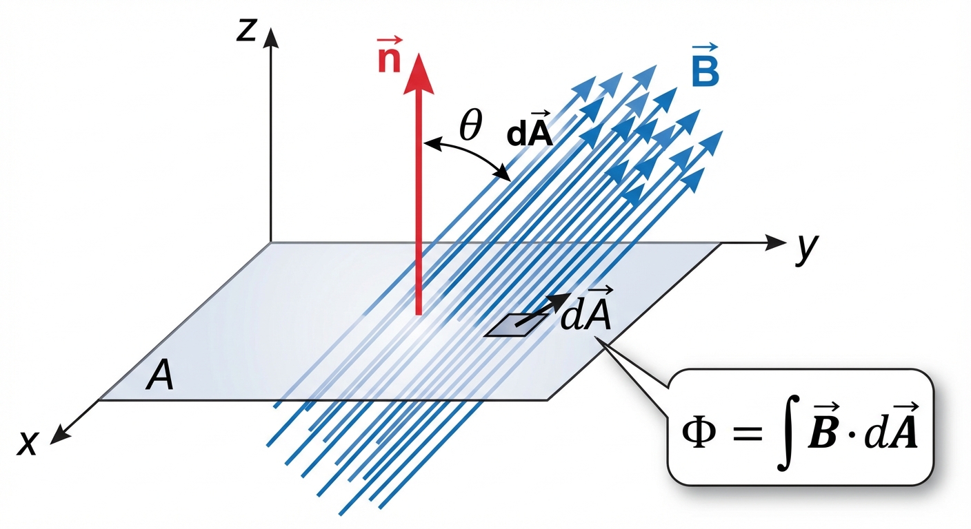
The magnetic flux through a differential area element $d\mathbf{A}$ is defined as the dot product of the magnetic field vector $\mathbf{B}$ and the area vector.
Where:
- $\Phi_B$ is the magnetic flux measured in Webers (Wb) ($1 \text{ Wb} = 1 \text{ T}\cdot\text{m}^2$).
- $\mathbf{B}$ is the magnetic field vector.
- $d\mathbf{A}$ is the vector normal (perpendicular) to the surface element.
- $\theta$ is the angle between $\mathbf{B}$ and the normal vector to the surface.
For a uniform magnetic field passing through a flat surface area $A$:
Gauss’s Law for Magnetism
One of Maxwell's four equations, Gauss's Law for Magnetism, states that the net magnetic flux through any closed surface is always zero.
Key Implications:
- Magnetic field lines are continuous loops; they do not begin or end.
- There are no magnetic monopoles (isolated north or south poles). If you cut a magnet in half, you get two smaller dipoles, not isolated poles.
Inductance and Inductors
While a capacitor opposes changes in voltage, an inductor is a circuit element that opposes changes in current. This property is called Inductance ($L$).
Self-Inductance Definition
Inductance stems from Faraday's Law of Induction. When current changes in a coil, the magnetic flux through that coil changes. This changing flux induces an electromotive force (EMF) that opposes the change in current (Lenz's Law).
We define the self-inductance $L$ of a device as the proportionality constant between the magnetic flux linkage and the current:
or
Where:
- $L$ is inductance, measured in Henries (H) ($1 \text{ H} = 1 \text{ Wb/A} = 1 \text{ T}\cdot\text{m}^2/\text{A}$).
- $N$ is the number of turns in the coil or loop.
- $\Phi_B$ is the flux through one turn.
- $I$ is the current.
Note: Like capacitance, inductance is a purely geometric property. It depends on the shape, size, and material of the device, not the current or voltage passing through it.
Induced EMF in an Inductor
Using Faraday's Law ($\mathcal{E} = -N \frac{d\Phi_B}{dt}$), we can relate EMF directly to inductance:
This equation is vital for circuit analysis. It tells us that an inductor acts like a battery facing "backwards" when current tries to increase, and pushes current forward when it tries to decrease.
Calculating Inductance for Standard Geometries
To find the inductance of a device in AP Physics C, follow these steps:
- Assume a current $I$.
- Determine the magnetic field $B$ produced by $I$ (using Ampere’s Law or Biot-Savart Law).
- Calculate the flux $\Phi_B = \int \mathbf{B} \cdot d\mathbf{A}$.
- Multiply by $N$ (total turns) to get flux linkage $N\Phi_B$.
- Divide by $I$ to isolate $L$.
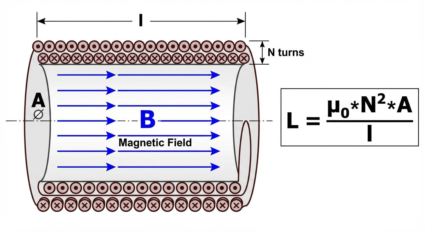
Example: Inductance of an Ideal Solenoid
Consider a solenoid of length $\ell$, cross-sectional area $A$, and total turns $N$.
- Magnetic Field: Inside a long solenoid, $B = \mu0 n I = \mu0 \frac{N}{\ell} I$.
- Flux: Since $B$ is uniform inside, $\PhiB = BA = \left( \mu0 \frac{N}{\ell} I \right) A$.
- Flux Linkage: Total flux linkage is $N\PhiB = N \left( \mu0 \frac{N}{\ell} I A \right) = \frac{\mu_0 N^2 A}{\ell} I$.
- Inductance: Divide by $I$.
Inductance of a Toroid (Rectangular Cross-Section)
For a toroid with inner radius $a$, outer radius $b$, height $h$, and $N$ turns:
- Field: Using Ampere's Law, $B(r) = \frac{\mu_0 N I}{2\pi r}$. (The field varies with radius $r$).
- Flux: Integrate over the cross-section. $dA = h \, dr$.
- Inductance: Apply $L = \frac{N\Phi_B}{I}$.
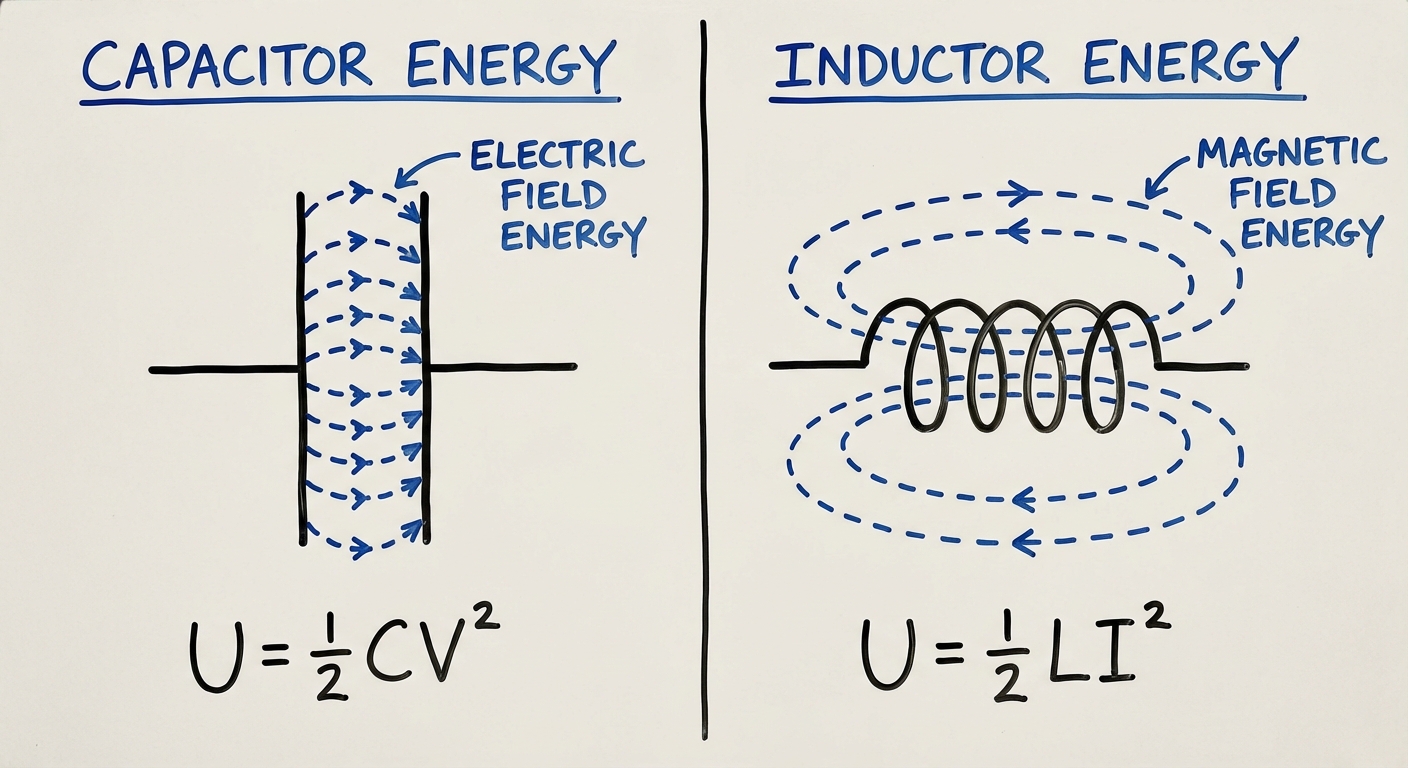
Energy Stored in a Magnetic Field
Just as capacitors store energy in an electric field, inductors store energy in a magnetic field. We derive this by calculating the power required to push current against the back EMF.
The work done (energy stored) is the integral of power over time:
Magnetic Energy Density
If we manipulate the energy equation using the solenoid formula ($L = \mu0 n^2 A \ell$) and field ($B = \mu0 n I$), we can find the energy stored per unit volume ($u_B$):
This formula applies generally to any region of space containing a magnetic field.
Summary Table: Capacitor vs. Inductor
| Feature | Capacitor ($C$) | Inductor ($L$) |
|---|---|---|
| Definition | Stores charge/Electric Energy | Stores flux/Magnetic Energy |
| Geometric Formula | $C = \frac{\kappa \epsilon_0 A}{d}$ (Parallel Plate) | $L = \frac{\mu_0 N^2 A}{\ell}$ (Solenoid) |
| Circuit Behavior | Opposes change in Voltage ($V$) | Opposes change in Current ($I$) |
| Fundamental Law | $I = C \frac{dV}{dt}$ | $\mathcal{E} = -L \frac{dI}{dt}$ |
| Energy | $U_E = \frac{1}{2}CV^2$ | $U_B = \frac{1}{2}LI^2$ |
| Energy Density | $uE = \frac{1}{2}\epsilon0 E^2$ | $uB = \frac{1}{2\mu0} B^2$ |
Common Mistakes & Pitfalls
Confusing Flux Linkage with Flux:
- Mistake: Calculating $L = \frac{\Phi_B}{I}$.
- Correction: Remember the $N$! The total flux "linked" by the coil is $N\PhiB$ (for a tightly wound coil). The formula is $L = \frac{N\PhiB}{I}$.
Angle $\theta$ in Flux Calculation:
- Mistake: Using the angle between the surface plane and the B-field.
- Correction: The angle $\theta$ is always between the normal vector (perpendicular to surface) and the B-field.
Inductance is Constant:
- Mistake: Thinking $L$ changes if current $I$ changes.
- Correction: For standard materials (non-ferromagnetic), $L$ is constant. Only geometry influences $L$. If $I$ doubles, $\Phi_B$ doubles, but the ratio $L$ stays the same.
Sign Errors in Vectors:
- Mistake: Ignoring the dot product orientation when calculating Flux through a closed surface.
- Correction: For closed surfaces (Gauss's Law), the area vector $d\mathbf{A}$ always points outward from the enclosed volume.
Assuming Uniform Field:
- Mistake: Using $\Phi = BA$ for toroids or wires.
- Correction: If $B$ depends on position (like $1/r$ in a toroid), you must integrate $\int B \, dA$ rather than multipling simply.