Comprehensive Guide to AP Physics 2 Unit 3: Electric Circuits
Electric Current and Resistance
Current: Describing the Flow
Electric Current ($I$) is defined as the rate at which electric charge flows through a cross-section of a conductor. While individual charge carriers (electrons) move somewhat randomly, an electric field creates a net motion known as drift velocity.
Two critical perspectives to distinguish:
- Conventional Current: The flow of positive charge (from high potential $+$ to low potential $-$). This is the standard used in circuit analysis.
- Electron Flow: Actual physical movement of electrons (from low potential $-$ to high potential $+$).
Formula:
- Symbol: $I$
- Unit: Amperes (A), where $1 \text{ A} = 1 \text{ C/s}$
Resistance and Resistivity
Resistance ($R$) is the opposition to the flow of charge. Think of it structurally using the water in a pipe analogy: a narrow pipe resists water flow more than a wide pipe.
Resistivity ($\rho$) is an intrinsic material property (how much a specific material, like Copper vs. Rubber, naturally resists electron flow), whereas Resistance is a property of a specific object (that specific copper wire).
Geometric Formula for Resistance:
Where:
- $\rho$ (rho) is the resistivity ($\Omega \cdot m$) — depends on material and temperature.
- $L$ is the length of the conductor ($m$).
- $A$ is the cross-sectional area ($m^2$).
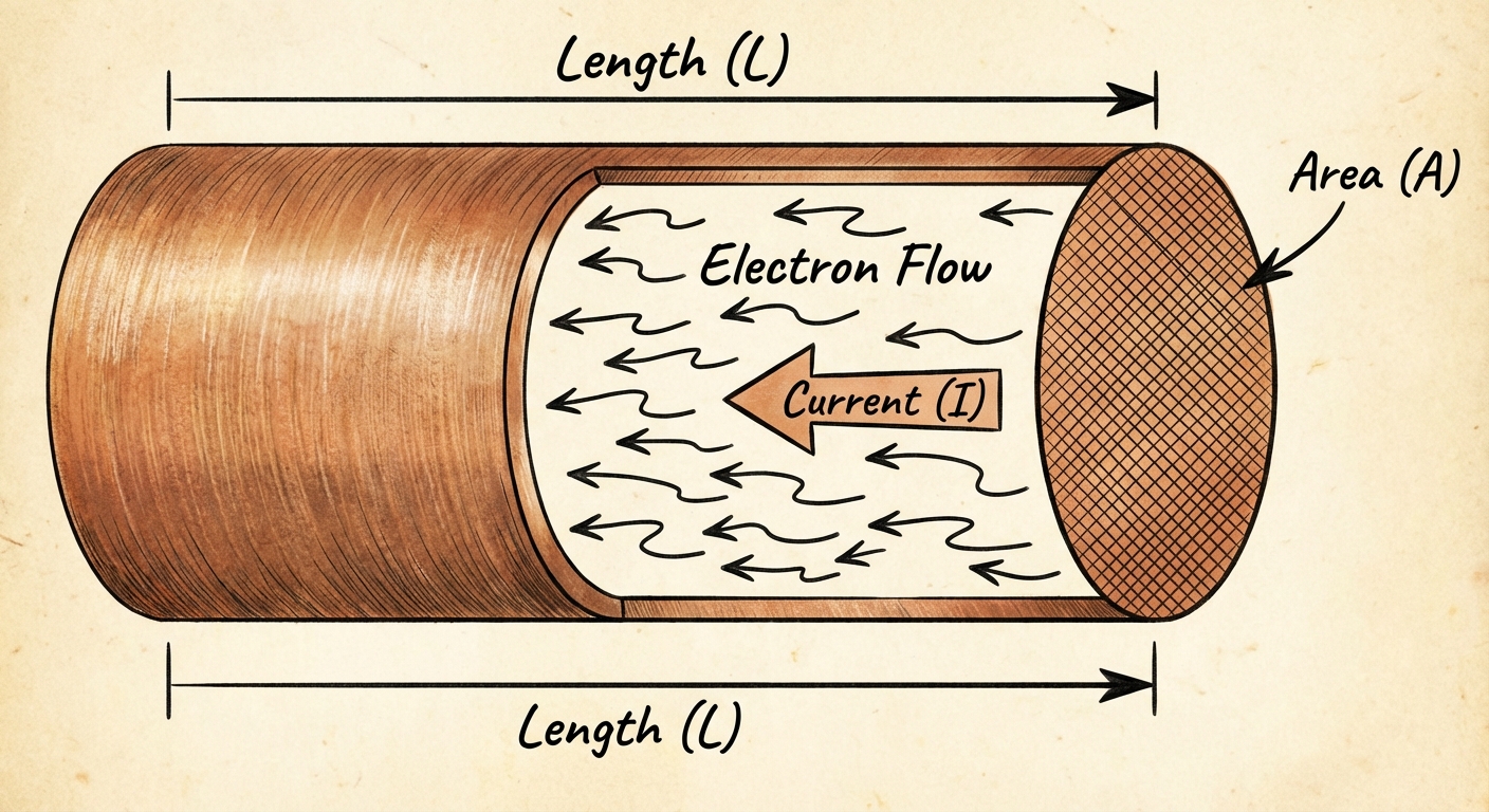
Key Relationships:
- Length: Doubling the length ($2L$) doubles the resistance ($2R$). usage.
- Area: Doubling the radius of a wire increases the area by a factor of 4 ($A = \pi r^2$), which decreases resistance by a factor of 4.
- Temperature: Generally, as temperature increases, resistivity increases (atoms vibrate more, obstructing electron flow).
Ohm’s Law and Electric Power
Defining Ohm’s Law
Ohm’s Law describes the relationship between Potential Difference (Voltage), Current, and Resistance. It states that for many materials, current is directly proportional to the applied voltage.
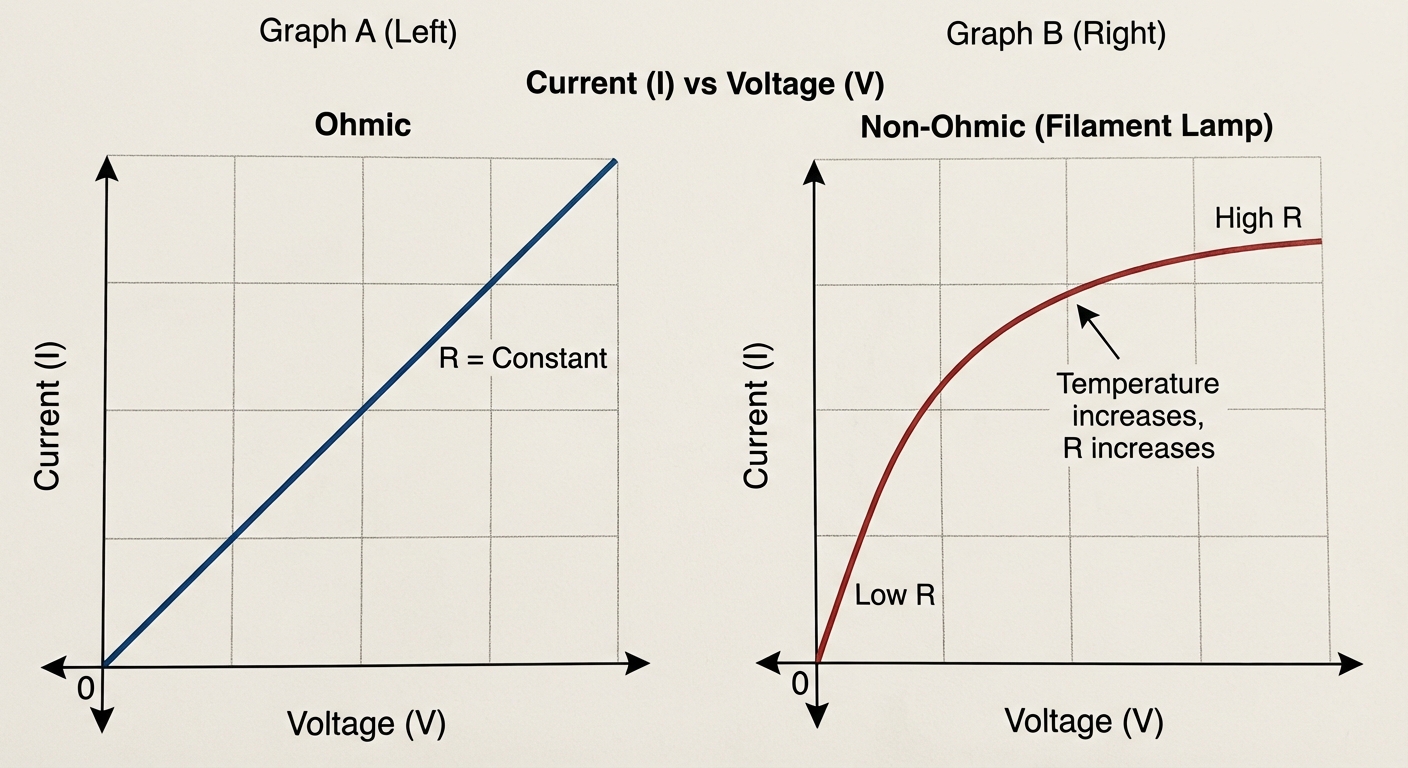
Ohmic vs. Non-Ohmic Materials
Not all devices follow Ohm's Law.
- Ohmic Devices: Resistance ($R$) is constant regardless of voltage. The graph of $I$ vs. $V$ is a straight line passing through the origin. The slope represents $1/R$ (or $R$ if plotting $V$ vs. $I$).
- Non-Ohmic Devices: Resistance changes as voltage/current changes. A lightbulb is a classic example; as it heats up, resistance increases, causing the $I$ vs. $V$ graph to curve (flatten out).
Electric Power
Power is the rate at which electrical energy is converted into other forms (heat, light, mechanical work). In physics exam problems involving lightbulbs, brightness is determined by power.
General Formula:
Derived Formulas (using Ohm's Law):
When dealing with resistors, you can substitute $\Delta V = IR$ to get:
- Unit: Watts (W), where $1 \text{ W} = 1 \text{ J/s}$
Kirchhoff’s Laws and Circuit Analysis
Circuit analysis relies on two fundamental conservation laws known as Kirchhoff's Laws.
1. Kirchhoff’s Junction Rule (Conservation of Charge)
The sum of currents entering any circuit junction must equal the sum of currents leaving that junction. Charge cannot accumulate at a point in the wire.
2. Kirchhoff’s Loop Rule (Conservation of Energy)
The sum of changes in potential (voltage bumps and drops) around any closed loop in a circuit must be zero. The battery provides energy (voltage gain), and resistors consume energy (voltage drop).
Sign Conventions for Loops:
- Crossing a battery from $-$ to $+$: Gain ($+\mathcal{E}$).
- Crossing a battery from $+$ to $-$: Drop ($-\mathcal{E}$).
- Crossing a resistor in the direction of current: Drop ($-IR$).
- Crossing a resistor against the direction of current: Gain ($+IR$).
Series and Parallel Circuits
Understanding how components behave in different configurations is essential for analyzing combination circuits.
Comparison Table
| Property | Series Circuits | Parallel Circuits |
|---|---|---|
| Arrangement | Components in a single path one after another | Components on separate branches sharing same nodes |
| Current ($I$) | Same through all components ($I{tot} = I1 = I_2$) | Splits based on resistance ($I{tot} = I1 + I_2$) |
| Voltage ($V$) | Splits/Divides ($V{source} = V1 + V_2$) | Same across each branch ($V{source} = V1 = V_2$) |
| Equiv. Resistance | Increases with more resistors | Decreases with more resistors |
| Formula | $R{eq} = R1 + R_2 + …$ | $\frac{1}{R{eq}} = \frac{1}{R1} + \frac{1}{R_2} + …$ |
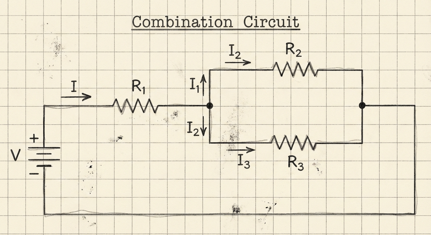
Analyzing Combination (Complex) Circuits
Most AP problems involve circuits with both series and parallel parts. To solve these:
- Redraw/Simplify: Identify small sections that are purely series or purely parallel.
- Calculate $R_{eq}$: Collapse the circuit step-by-step into a single equivalent resistor.
- Find Total Current: Use ohm's law ($I{tot} = \mathcal{E} / R{eq_{total}}$).
- Work Backwards: Expand the circuit back out to find specific voltage drops or currents using the rules in the table above.
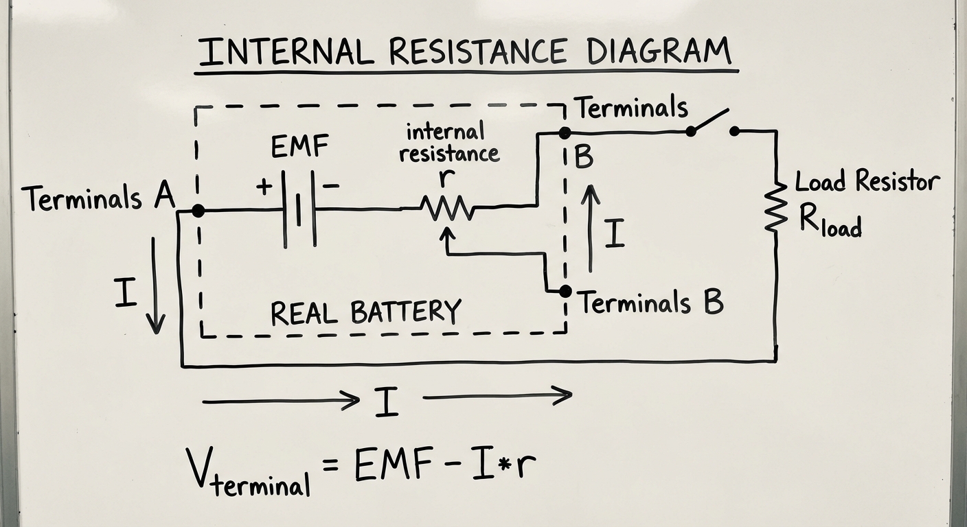
Real Batteries and Internal Resistance
In ideal scenarios, batteries maintain a constant potential difference. In reality, batteries have Internal Resistance ($r$).
EMF vs. Terminal Voltage
- EMF ($\mathcal{E}$): The electromotive force. The maximum theoretical voltage the battery can provide (when no current flows).
- Terminal Voltage ($V_T$): The actual voltage measured across the battery terminals when the circuit is running.
Equation:
As current ($I$) increases, the voltage drop across the internal resistance ($Ir$) increases, causing the terminal voltage available to the rest of the circuit to decrease.
Measurement Tools
- Voltmeter: Measures potential difference. Must be connected in Parallel. Ideal resistance = $\infty$ (so no current flows through it).
- Ammeter: Measures current. Must be connected in Series. Ideal resistance = $0$ (so it doesn't affect the circuit).
Capacitors in Circuits (Steady State & RC)
Capacitors in Series and Parallel
Capacitors follow the reverse logic of resistors when combining them.
- Capacitors in Parallel: $C{eq} = C1 + C_2$ (Area increases, storing more charge).
- Capacitors in Series: $\frac{1}{C{eq}} = \frac{1}{C1} + \frac{1}{C_2}$ (Effective plate separation increases, storing less charge).
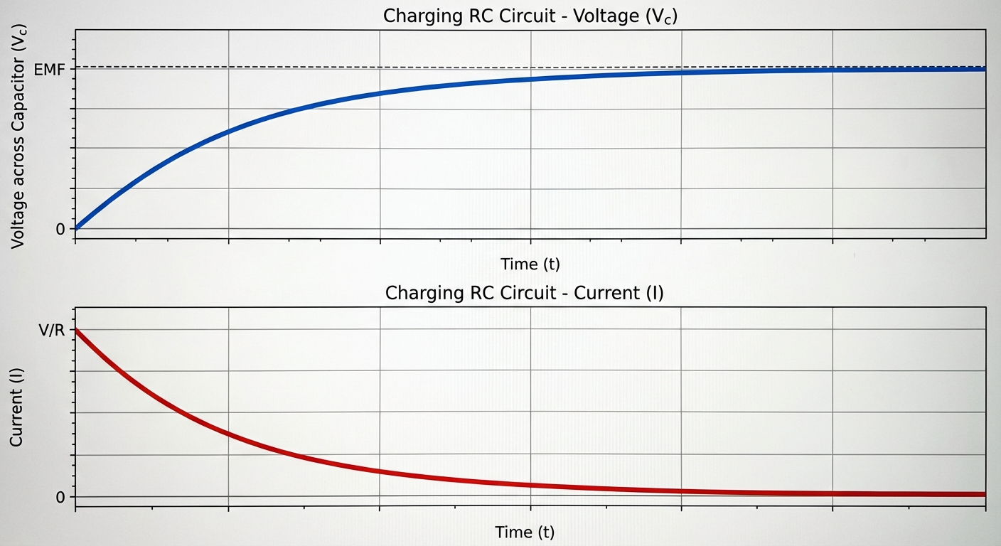
RC Circuits (Transient Behavior)
An RC circuit contains Resistors and Capacitors. The behavior changes over time as the capacitor charges or discharges.
Qualitative Analysis (The "Switch" Logic)
At $t=0$ (Immediately after switch closes):
- The uncharged capacitor offers zero opposition to voltage.
- It acts like a wire (Short Circuit).
- Current is maximum: $I_0 = \mathcal{E}/R$.
At $t = \infty$ (After a long time/Steady State):
- The capacitor is fully charged.
- It acts like a break in the wire (Open Circuit).
- Current is zero: $I = 0$.
- Voltage across capacitor equals the battery voltage (if in simple series).
Quantitative Analysis
The charging/discharging process follows an exponential curve governed by the Time Constant ($\tau$).
- $\tau$: The time it takes to charge to $\approx 63\%$ of max voltage, or discharge to $\approx 37\%$ of initial voltage.
Formulas (Charging):
Note: $V$ starts at 0 and curves up to max; $I$ starts at max and curves down to 0.
Common Mistakes & Pitfalls
- Confusing Series/Parallel Rules: Students often swap the resistance simplification rules for resistors with those for capacitors. Remember: Resistors in Series add; Capacitors in Series add inversely.
- Misapplying $V=IR$: Ohm's law applies to the specific component, not just the whole circuit. If you want current through Resistor 2, you must use Voltage across Resistor 2, not the battery voltage ($I2 = V2/R_2$).
- Junction Rule Errors: In complex circuits, students forget that current splits. If two branches have different resistances, the current does not split 50/50.
- Bulb Brightness Logic: When asked about brightness, always analyze Power ($P=I^2R$ or $P=V^2/R$). A common trap involves a parallel bulb burning out; students assume the remaining bulb changes brightness. In an ideal parallel circuit with a battery, the remaining branch still sees the same Voltage, so its brightness is unchanged.
- Steady State RC Circuits: Students often try to calculate current flowing through a fully charged capacitor branch. Remember, in DC steady state, $I_{capacitor_branch} = 0$.