Comprehensive Guide to Conductors, Capacitors, and Dielectrics
Unit 2 Overview: Electrostatics in Conductors and Dielectrics
This unit bridges the gap between abstract electric fields (Unit 1) and practical circuits (Unit 3). In AP Physics C: Electricity and Magnetism, understanding how charge behaves on material objects—specifically conductors and insulators—is critical. You will move from calculating fields produced by point charges to fields influencing charge distributions on macroscopic objects and storing potential energy.
Conductors in Electrostatic Equilibrium
A conductor is a material containing charge carriers (usually electrons) that are free to move. Electrostatic Equilibrium is the state reached when all net charge movements have ceased. Even if the conductor is placed in an external electric field, it will shift its charges almost instantly until equilibrium is reached.
Four Essential Rules of Conductors
For any conductor in electrostatic equilibrium, the following rules apply without exception:
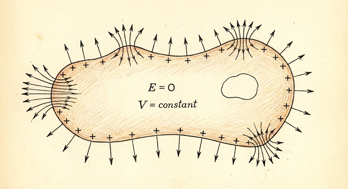
The Electric Field Inside is Zero:
If there were an electric field inside ($E \neq 0$), it would exert a force ($F=qE$) on the free electrons, causing them to accelerate. Since the charges are stationary in equilibrium, the net force—and therefore the field—must be zero.Net Charge Resides on the Surface:
Because like charges repel, excess charge tries to get as far away from other excess charge as possible. Using Gauss's Law with a Gaussian surface drawn just inside the boundary of the conductor (where $E=0$), the enclosed flux is zero, meaning the enclosed charge must be zero. Therefore, all excess charge is pushed to the exterior surface.Electric Field is Perpendicular to the Surface:
Just outside the conductor, the electric field vector must be normal (perpendicular) to the surface. If there were a parallel component, it would push surface charges along the surface, violating equilibrium.
The magnitude of this field is given by:
where $\sigma$ is the surface charge density.The Entire Conductor is an Equipotential:
Since $E = -dV/dr$ and $E=0$ inside, the derivative of the potential is zero. This means $V$ is constant throughout the volume and on the surface. No work is done moving a charge along the surface of a conductor.
Conductors with Cavities
Things get interesting when a conductor has a hole (cavity) in it.
- Empty Cavity: If there is no charge inside the cavity, $E=0$ inside the cavity, and there is no charge on the inner wall.
- Charge Inside Cavity: If a point charge $+Q$ is placed inside an isolated cavity, it attracts $-Q$ to the inner wall to shield the rest of the metal. Because the net charge of the conductor is conserved, $+Q$ will appear on the outer surface (assuming the conductor was originally neutral).
Capacitance and Geometry
A capacitor is a device used to store electric potential energy and electric charge. It typically consists of two conductors separated by an insulator (or vacuum).
Definition of Capacitance
Capacitance ($C$) measures how much charge ($Q$) a system can store for a given potential difference ($\Delta V$). It is a geometric property, meaning it depends only on the shape and material of the capacitor, not on the actual voltage applied.
- Unit: Farad (F), where $1 \text{ F} = 1 \text{ C} / 1 \text{ V}$.
Calculating Capacitance: The Step-by-Step Method
To find the capacitance of any geometry derivation-style (common on FRQs):
- Assume a charge of $+Q$ on one plate and $-Q$ on the other.
- Use Gauss's Law to find the Electric Field ($E$) between the conductors in terms of $Q$.
- Calculate the potential difference $|\Delta V| = \int \vec{E} \cdot d\vec{r}$ moving from the negative to the positive conductor.
- Divide $Q$ by the magnitude of $\Delta V$.
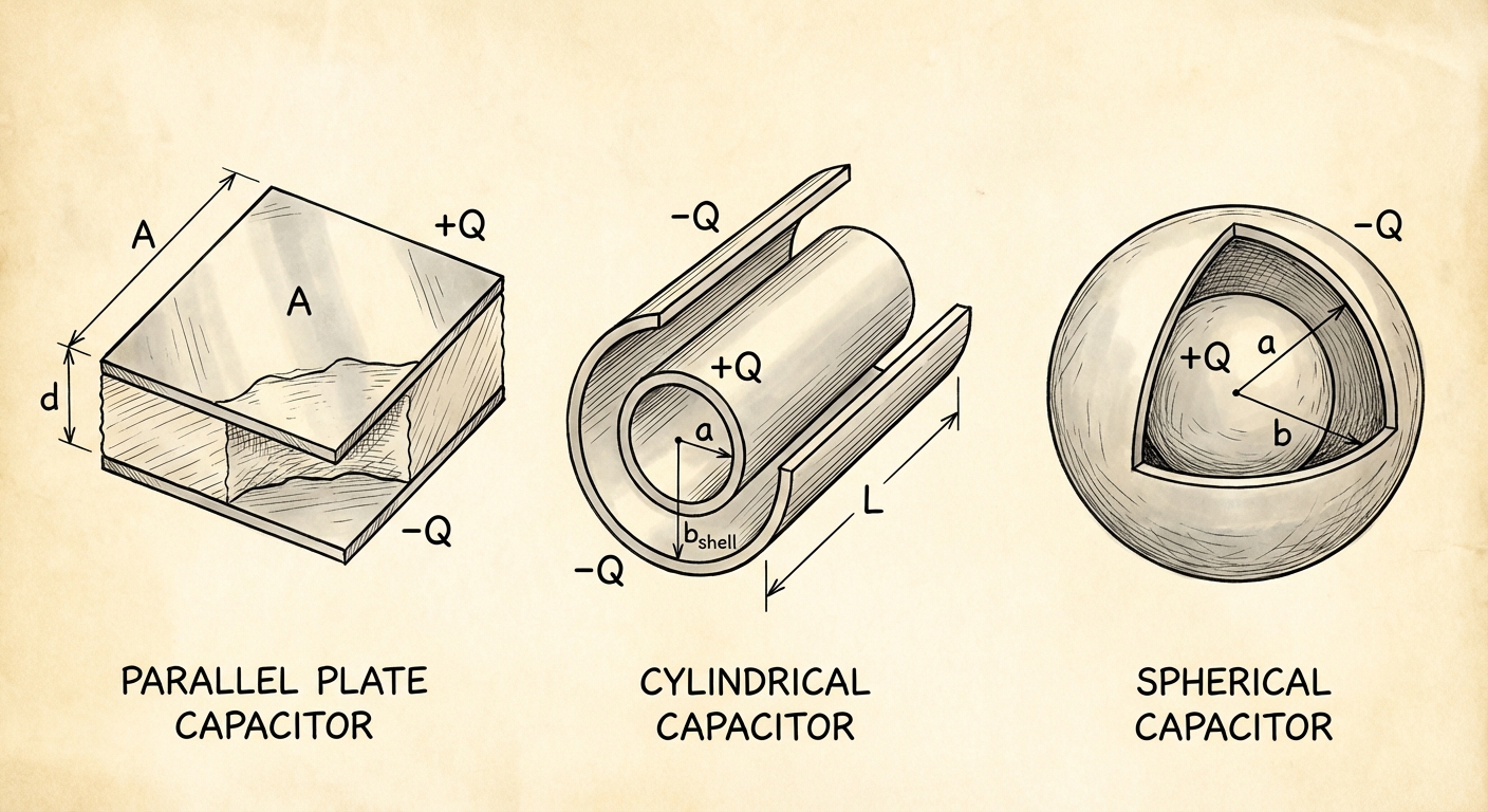
Parallel Plate Capacitors
For two plates of area $A$ separated by distance $d$:
- Field: $E = \frac{\sigma}{\epsilon0} = \frac{Q}{\epsilon0 A}$ (field is uniform).
- Potential: $\Delta V = E \cdot d = \frac{Qd}{\epsilon_0 A}$.
- Capacitance:
Cylindrical Capacitors
A central wire of radius $a$ surrounded by a conductive shell of radius $b$ and length $L$
- Field: Using a cylindrical Gaussian surface, $E = \frac{\lambda}{2\pi\epsilon0 r} = \frac{Q}{2\pi\epsilon0 L r}$.
- Potential: Integrating $E$ from $a$ to $b$ yields $\Delta V = \frac{Q}{2\pi\epsilon_0 L} \ln(\frac{b}{a})$.
- Capacitance:
Spherical Capacitors
An inner sphere radius $a$ and outer shell radius $b$:
- Field: Acts like a point charge, $E = \frac{Q}{4\pi\epsilon_0 r^2}$.
- Potential: $\Delta V = \frac{Q}{4\pi\epsilon_0}(\frac{1}{a} - \frac{1}{b})$.
- Capacitance:
Special Case: An isolated sphere (where shell $b \to \infty$) has capacitance $C = 4\pi\epsilon_0 R$.
Capacitor Circuits and Energy
When connecting multiple capacitors, we analyze them using Equivalent Capacitance ($C_{eq}$).
Parallel Combination
Capacitors connected side-by-side across the same potential difference.
- Voltage: Same for all ($V1 = V2 = V$).
- Charge: Splits ($Q{total} = Q1 + Q_2$).
- Formula:
- Memory Aid: Capacitors in parallel add up to a larger area plate, increasing capacity.
Series Combination
Capacitors connected in a single path.
- Charge: Same for all ($Q1 = Q2 = Q$). The charge induced on one plate forces charge onto the next.
- Voltage: Splits ($V{total} = V1 + V_2$).
- Formula:
- Note: The equivalent capacitance in series is always less than the smallest individual capacitor.
Energy Stored in Capacitors
Work must be done to separate charges and place them on the plates. This work is stored as Potential Energy ($U_C$).
- Energy Density ($uE$): The energy is actually stored in the electric field between the plates. The energy per unit volume is:
Dielectrics
A dielectric is an insulating material placed between capacitor plates. It increases the capacitance by a factor called the dielectric constant ($\kappa$, kappa).
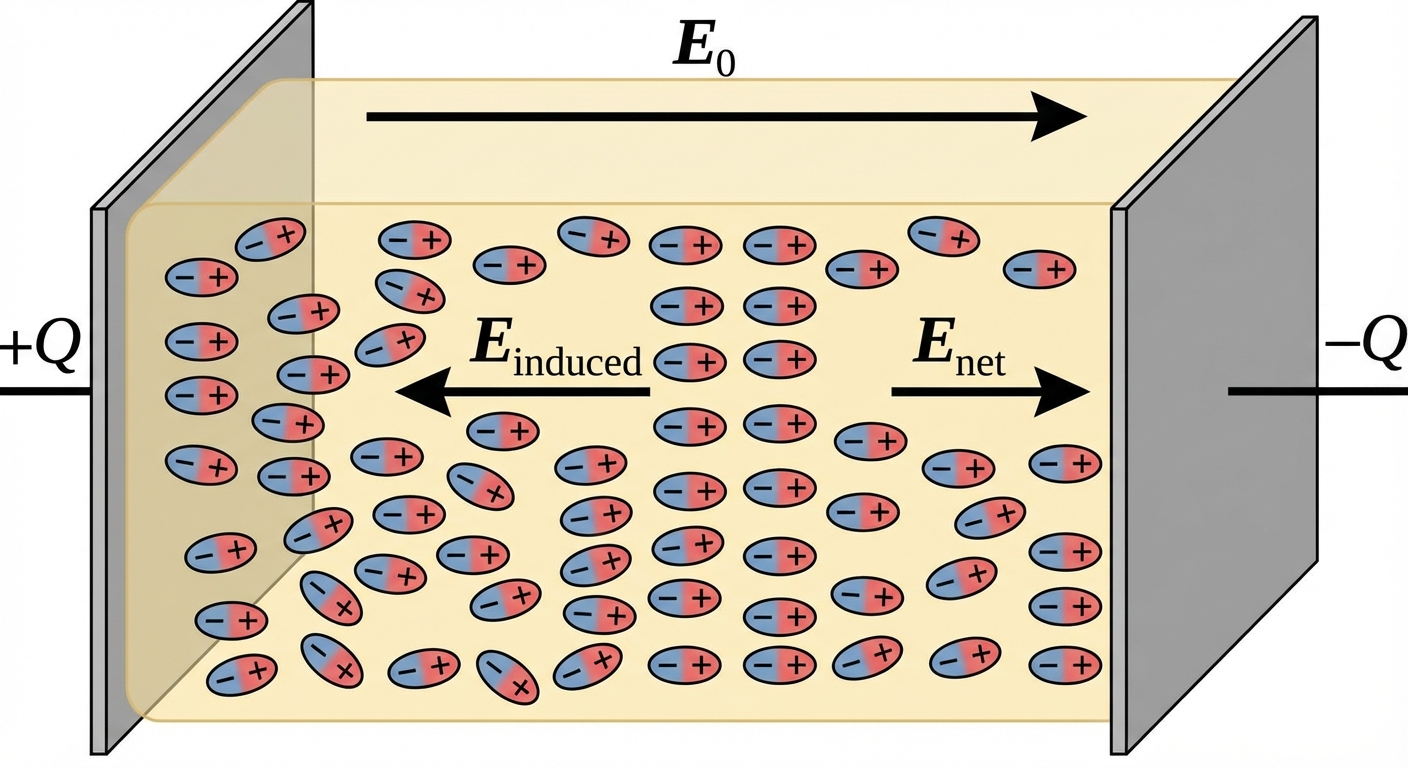
Polarization Mechanism
Dielectrics contain dipoles (polar molecules). When placed in an external E-field:
- The positive ends of the molecules align with the E-field.
- This creates a small internal "induced" field ($E_{ind}$) pointing opposite to the external field.
- Net Field Reduced: $E{net} = E{vaccum} - E_{ind}$.
Because the field strength drops for the same charge, the voltage drops ($V = Ed$), and since $C = Q/V$, the capacitance increases.
(where $\kappa \geq 1$)
Two Scenarios: Battery Connected vs. Disconnected
This is the most common conceptual trap in Unit 2.
| Battery DISCONNECTED (Isolated) | Battery CONNECTED (Constant V) | |
|---|---|---|
| Constraint | Charge (Q) is constant (Charge has nowhere to go) | Voltage (V) is constant (Maintained by battery) |
| Effect of adding Dielectric | $C$ increases ($\kappa$) | $C$ increases ($\kappa$) |
| Charge (Q) | Constant ($Q_0$) | Increases ($\kappa Q_0$) |
| Voltage (V) | Decreases ($V_0 / \kappa$) | Constant ($V_0$) |
| Electric Field (E) | Decreases ($E_0 / \kappa$) | Constant ($E_0$) (Since $V$ and $d$ are fixed) |
| Stored Energy (U) | Decreases ($U_0 / \kappa$) | Increases ($\kappa U_0$) |
Common Mistakes & Pitfalls
Confusing Potential with Field in Conductors:
- Mistake: Thinking potential is zero inside a conductor because the field is zero.
- Correction: $E=0$ implies potential is constant, not necessarily zero. If the surface is at 100V, the center is at 100V.
Series/Parallel Resistor vs. Capacitor Formulas:
- Mistake: Using resistor formulas for capacitors.
- Correction: They are opposites. Capacitors in Parallel add directly ($CP = \sum Ci$). Capacitors in Series add inversely.
Dielectric Insertion Energy:
- Mistake: Assuming energy always increases when a dielectric is inserted.
- Correction: If the capacitor is isolated (disconnected), the dielectric is "sucked in" by the field, doing work on the dielectric, thereby lowering the stored potential energy of the system.
Points and Charge Density:
- Mistake: Assuming charge is evenly distributed on an irregular shaped conductor.
- Correction: Charge accumulates more densely at sharp points (small radius of curvature). This creates a stronger E-field at sharp tips (lightning rod principle).