Unit 6: Waves, Sound, and Physical Optics - Section Guide
Physical Optics: The Wave Nature of Light
Unlike geometric optics, which treats light as rays moving in straight lines, Physical Optics focuses on the behavior of light as a wave. This section explains phenomena that ray optics cannot: how light bends around corners (diffraction), how light waves overlap (interference), and how soap bubbles create rainbows (thin film interference).
Interference and Diffraction Principles
The Superposition Principle
At the heart of physical optics is the Principle of Superposition. When two or more waves overlap, the resultant displacement at any point is the sum of the individual displacements.
- Constructive Interference: Occurs when waves meet "in phase" (crest meets crest). The amplitude increases (brighter light).
- Destructive Interference: Occurs when waves meet "out of phase" (crest meets trough). The amplitude cancels out (darkness).
Coherence and Monochromatic Light
To observe stable interference patterns, two conditions are usually required:
- Monochromatic: The light has a single wavelength (color).
- Coherent: The waves maintain a constant phase relationship relative to each other (i.e., they don't jitter randomly).
Path Length Difference ($\Delta L$)
Whether interference is constructive or destructive depends on the difference in distance two waves travel to reach a specific point. This is called the Path Length Difference ($\Delta L$).
- Constructive Condition: $\Delta L = m\lambda$ (where $m = 0, 1, 2…$)
- Destructive Condition: $\Delta L = (m + \frac{1}{2})\lambda$
Young’s Double-Slit Experiment
In 1801, Thomas Young proved the wave nature of light by shining light through two parallel slits. Instead of two bright spots appearing on the screen behind the slits, an interference pattern of alternating bright and dark fringes appeared.
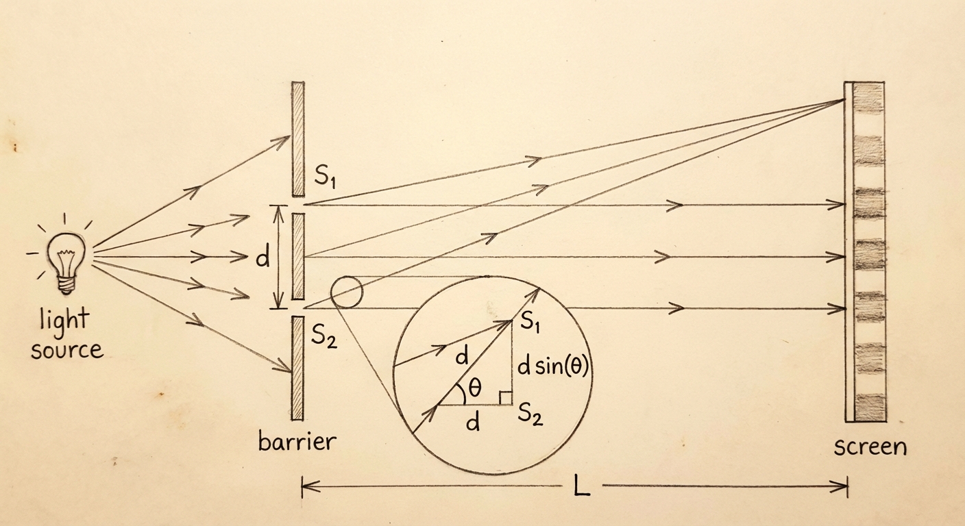
The Geometry of Interference
Consider two slits separated by distance $d$. Light travels a distance $L$ to a screen. We analyze a point on the screen located at an angle $\theta$ from the center line.
Because the screen is usually very far away ($L \gg d$), the light rays traveling from the two slits are essentially parallel. The extra distance the bottom ray travels is the Path Length Difference:
Calculating Maxima and Minima
1. For Bright Fringes (Maxima):
Constructive interference occurs when the path difference is a whole number of wavelengths.
Where:
- $m$ is the order number ($0$ is the central bright spot, $\pm 1$ are the first bright spots to the sides, etc.).
2. For Dark Fringes (Minima):
Destructive interference occurs when the path difference is a half-integer multiple.
Linear Location on Screen ($y$)
If the angle $\theta$ is small (which it usually is in usually $< 10^\circ$), we can use the small-angle approximation: $\sin \theta \approx \tan \theta \approx \frac{y}{L}$.
This yields the formula for the position $y$ of the fringes on the screen:
- $y_m$: Distance from the central maximum to the $m$-th bright fringe.
- $L$: Distance from slits to screen.
- $d$: Distance between the two slits.
Diffraction: Single Slit and Gratings
Diffraction is the bending of waves around obstacles or through openings.
Single-Slit Diffraction
Even a single slit produces an interference pattern because light waves from different parts of the same slit interfere with each other.
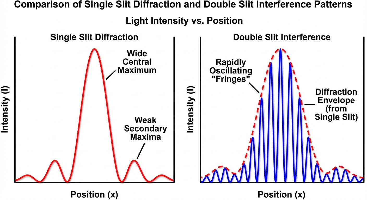
Key Differences from Double-Slit:
- The Central Maximum is twice as wide and much brighter than the secondary maxima.
- The intensity of secondary bright fringes drops off very rapidly.
Formula for Single-Slit MINIMA (Dark Spots):
Note the distinct variable $D$ or $a$ (slit width) instead of $d$ (slit spacing).
- Alert: In single-slit, integer $m$ values indicate dark spots (minima), not bright spots. There is no $m=0$ minima; the center is bright.
Diffraction Gratings
A diffraction grating has thousands of slits. The physics is identical to the Double-Slit experiment, but the maxima are sharper, narrower, and brighter.
- Formula: $d \sin \theta = m\lambda$ (Same as double-slit).
- Use: Gratings are used in spectrometers to separate light into its component colors (wavelengths) very precisely.
Thin Film Interference
This phenomenon causes the rainbows seen in oil slicks or soap bubbles. It occurs when light reflects off the top and bottom surfaces of a thin transparent layer.
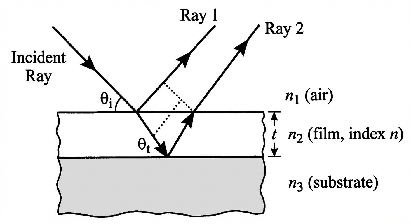
Phase Changes Upon Reflection
Before doing math, you must check for phase changes (flips).
- "Hard" Reflection: When light reflects off a medium with a higher index of refraction ($n{low} \to n{high}$), the wave undergoes a $180^\circ$ ($\pi$ or $\lambda/2$) phase shift.
- Mnemonic: "Low to High, Phase Shift Pi."
- "Soft" Reflection: When light reflects off a medium with a lower index of refraction ($n{high} \to n{low}$), there is no phase shift.
The Rules
Let $t$ be the thickness of the film and $\lambda{film} = \frac{\lambda{vacuum}}{n}$ be the wavelength inside the film.
The total path difference is traveling down and up the film: $2t$. We must combine this with the phase shifts.
Case A: 0 or 2 Phase Shifts (e.g., Soap bubble in air)
- Constructive: $2t = (m + \frac{1}{2})\frac{\lambda}{n}$
- Destructive: $2t = m \frac{\lambda}{n}$
Case B: 1 Phase Shift (e.g., Oil on water, or Anti-reflective coating on glass)
- Constructive: $2t = m \frac{\lambda}{n}$
- Destructive: $2t = (m + \frac{1}{2})\frac{\lambda}{n}$
Note: Case B effectively flips the standard interference logic because the phase shift acts like an extra half-wavelength of distance.
Worked Example: Anti-Reflective Coating
Problem: A lens ($n{glass} = 1.50$) is coated with a thin film of magnesium fluoride ($n{coating} = 1.38$). What is the minimum thickness $t$ required to minimize reflection for green light ($\lambda = 550$ nm)?
Solution:
- Analyze Reflections:
- Top surface (Air $n\approx 1$ to Coating $n=1.38$): Low to High $\rightarrow$ Phase Shift.
- Bottom surface (Coating $n=1.38$ to Glass $n=1.50$): Low to High $\rightarrow$ Phase Shift.
- Count Shifts: 2 Phase Shifts. We are in "Case A" territory (standard logic).
- Choose Condition: We want to minimize reflection. This implies Destructive Interference.
- Formula: For 2 shifts, Destructive is $2t = (m + \frac{1}{2}) \frac{\lambda}{n}$.
- Wait! Check the rules again.
- Rule check: If we have 0 or 2 shifts, the two rays are already "in sync" regarding phase flips. Therefore, the path difference $2t$ must provide the half-wavelength offset to destroy the light.
- Correct Formula: $2t = (m + \frac{1}{2}) \frac{\lambda}{n}$.
- Calculate:
- Use minimum thickness, so $m=0$.
- $2t = \frac{1}{2} \frac{\lambda}{n}$
- $t = \frac{\lambda}{4n}$
- $t = \frac{550 \text{ nm}}{4(1.38)} \approx 99.6 \text{ nm}$.
Common Mistakes & Exam Pitfalls
- Mixing up Single and Double Slit Formulas:
- Double Slit ($d\sin\theta = m\lambda$): Integer $m$ is for MAXIMA.
- Single Slit ($a\sin\theta = m\lambda$): Integer $m$ is for MINIMA.
- Forgetting Wavelength Changes in Media: In thin films, you must use $\lambda{film} = \lambda{vacuum} / n$. If you use the air wavelength for the path difference calculation, your answer will be wrong.
- Confusing Slit Width ($a$) and Slit Separation ($d$): Read the problem carefully. $d$ is the distance between slits; $a$ (or $w$) is the width of the opening itself.
- Small Angle Approximation Invalidity: If the angle $\theta$ is large ($>10^\circ$), you cannot use $y = \frac{m\lambda L}{d}$. You must calculate $\theta = \sin^{-1}(m\lambda/d)$ and then use $y = L \tan \theta$.