Energy Dissipation and Storage in Electric Circuits
Electrical Power
In electric circuits, energy is continuously transformed. Batteries convert chemical potential energy into electrical potential energy, and components like resistors (or light bulbs) convert that electrical energy into heat and light. Electric Power ($P$) measures the rate at which this electrical energy is converted or transferred.
Defining Electric Power
The fundamental definition of power is the work done per unit of time ($P = \frac{\Delta E}{\Delta t}$). In the context of a circuit element with a potential difference $\Delta V$ and a current $I$, the power is given by:
Using Ohm's Law ($\Delta V = IR$), we can derive two alternative forms that are specifically useful for resistors (ohmic devices):
In terms of Current and Resistance:
Use this when elements are in Series, because Current ($I$) is constant for all components.In terms of Voltage and Resistance:
Use this when elements are in Parallel, because Voltage ($\Delta V$) is constant across branches.
Light Bulb Brightness
A classic AP Physics 2 exam question involves ranking the brightness of light bulbs. Brightness is directly proportional to the Power dissipated by the bulb.
- If bulbs are identical (same Resistance $R$), you can compare either the Current passing through them ($I$) or the Voltage drop across them ($\Delta V$).
- Higher Current $\rightarrow$ Brighter Bulb
- Higher Voltage Drop $\rightarrow$ Brighter Bulb
Worked Example: Power Dissipation
Scenario: A $12\,V$ battery is connected to a $6\,\Omega$ resistor.
- Calculate the power dissipated.
- If a second $6\,\Omega$ resistor is added in series, calculate the new power dissipated by the original resistor.
Solution:
Single Resistor:
Two Resistors in Series:
First, find the new equivalent resistance: $R{eq} = 6\,\Omega + 6\,\Omega = 12\,\Omega$. Next, find the total current: $I{tot} = \frac{\Delta V}{R_{eq}} = \frac{12}{12} = 1\,A$.
Now, calculate power for the single original resistor using $I=1\,A$:
Note: Adding a resistor in series increased total resistance, decreased current, and significantly dropped the power dissipated by the first bulb (it gets dimmer).
Capacitance and Capacitors
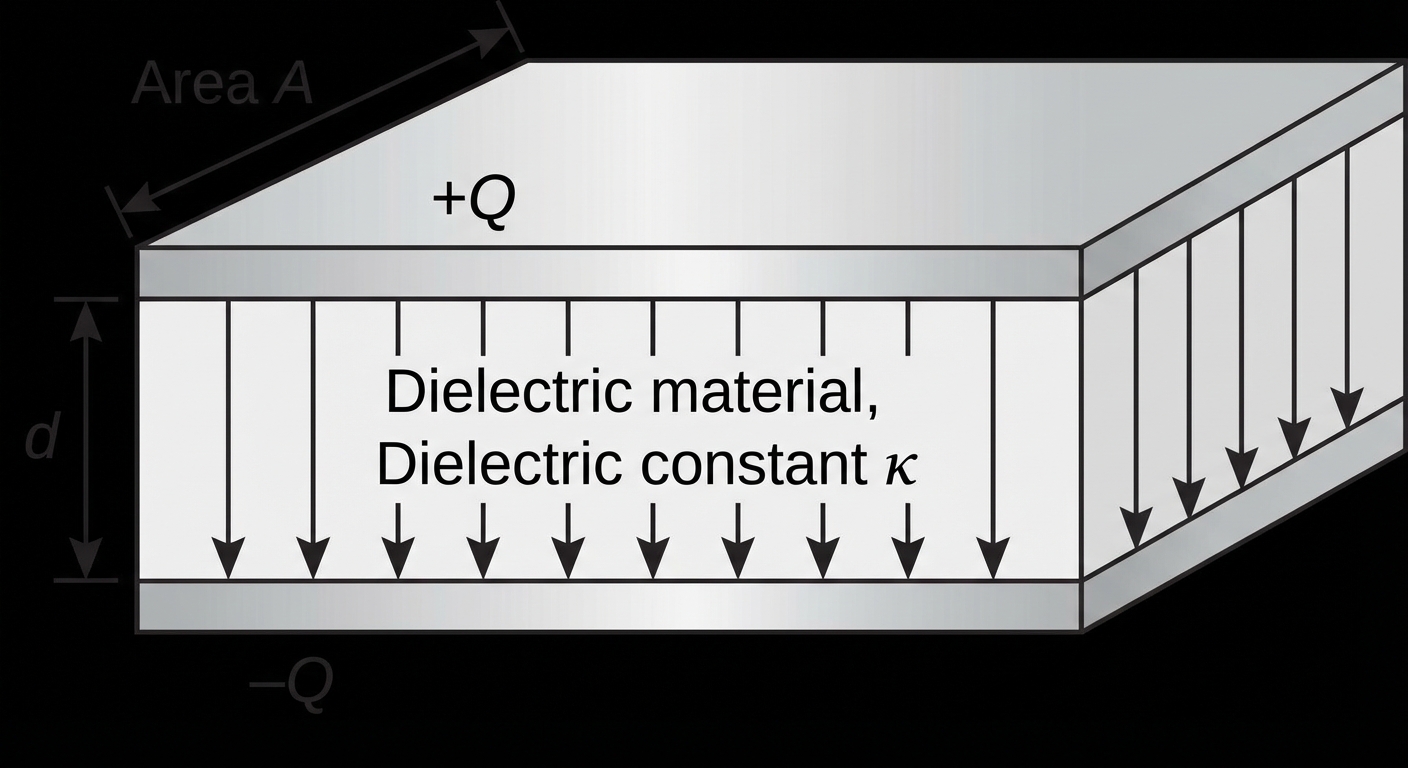
A capacitor is a device used to store electrical potential energy in an electric field. The standard capacitor used in AP Physics 2 is the Parallel Plate Capacitor.
Geometry and Dielectrics
The Capacitance ($C$) of a parallel plate capacitor tells us how much charge it can store per unit of voltage. It is determined purely by its physical geometry and the material between the plates.
- $\kappa$ (kappa): The Dielectric Constant of the material between plates ($> 1$ for insulators, $= 1$ for vacuum/air).
- $\epsilon_0$: The permittivity of free space ($8.85 \times 10^{-12} \, F/m$).
- $A$: Area of one plate ($m^2$).
- $d$: Distance between the plates ($m$).
Charge and Energy
Once a capacitor is connected to a voltage source, charge accumulates on the plates ($+Q$ on one, $-Q$ on the other) until the potential difference across the capacitor equals the potential difference of the source.
Charge Relationship:
Energy Stored in a Capacitor ($U_C$):
Because it takes work to push like charges onto a plate against repulsive forces, capacitors store energy. Integrating the work done yields three equivalent equations:
Capacitors in Circuits (RC Circuits)
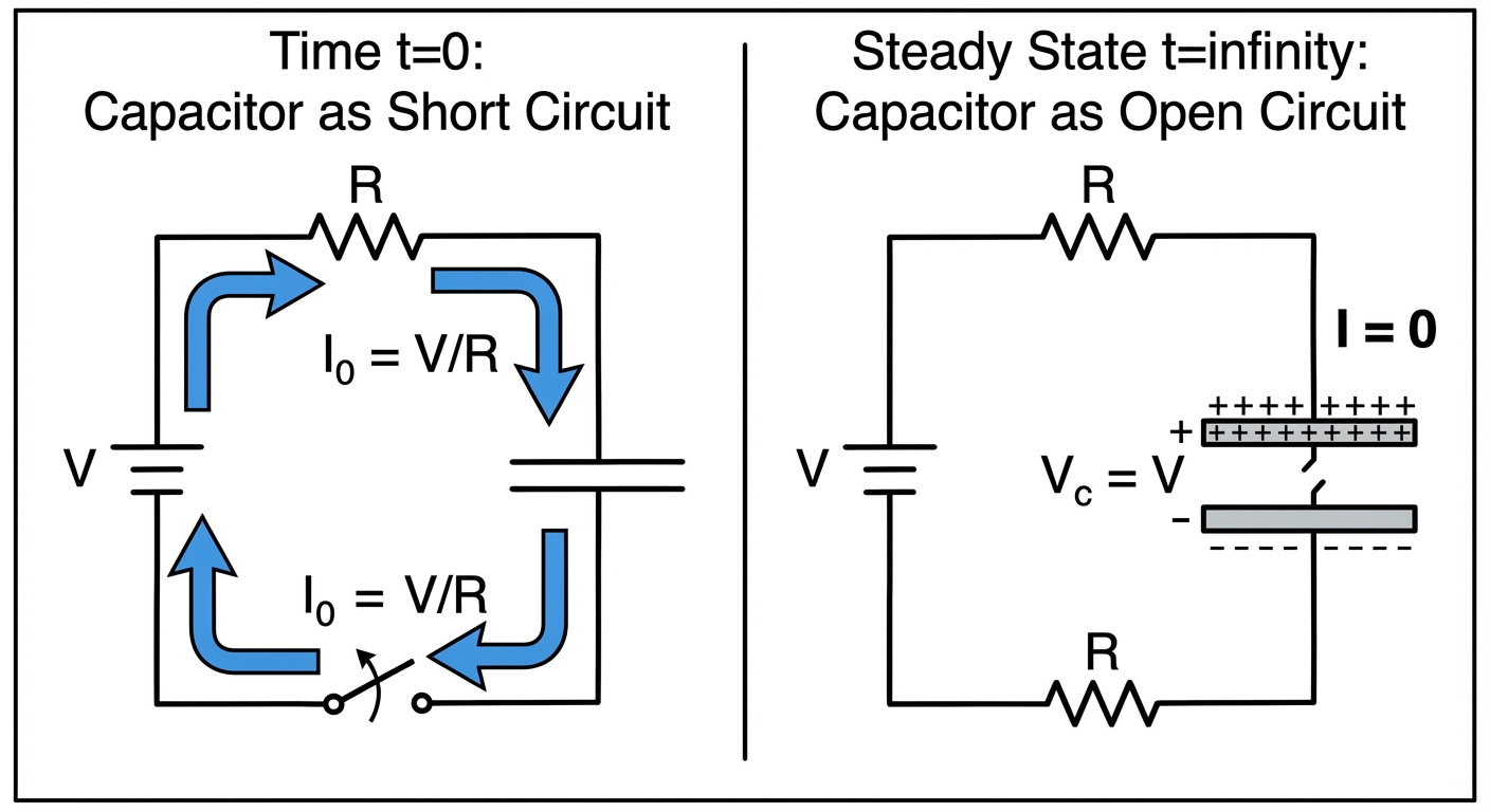
In AP Physics 2, you must understand how capacitors behave in DC circuits specifically at two moments in time: immediately after a switch is thrown ($t=0$) and after a long time ($t \to \infty$).
1. Transient State ($t=0$)
Immediately after a switch closes on an uncharged capacitor:
- The capacitor offers effectively zero resistance to the flow of current because there is no accumulated charge to repel new flowing charge.
- Behavior: The capacitor acts like a plain wire (a short circuit).
- $\Delta V_C = 0$
- Current is at its maximum: $I_{max} = \frac{\mathcal{E}}{R}$.
2. Steady State ($t \to \infty$)
After a long time, the capacitor becomes fully charged.
- The plates are saturated with charge. No more current can flow onto them.
- Behavior: The capacitor acts like an open switch (a broken wire).
- Current in the branch containing the capacitor is zero.
- The voltage across the capacitor is constant. If connected simply in series with a battery, $\Delta VC = \mathcal{E}{battery}$.
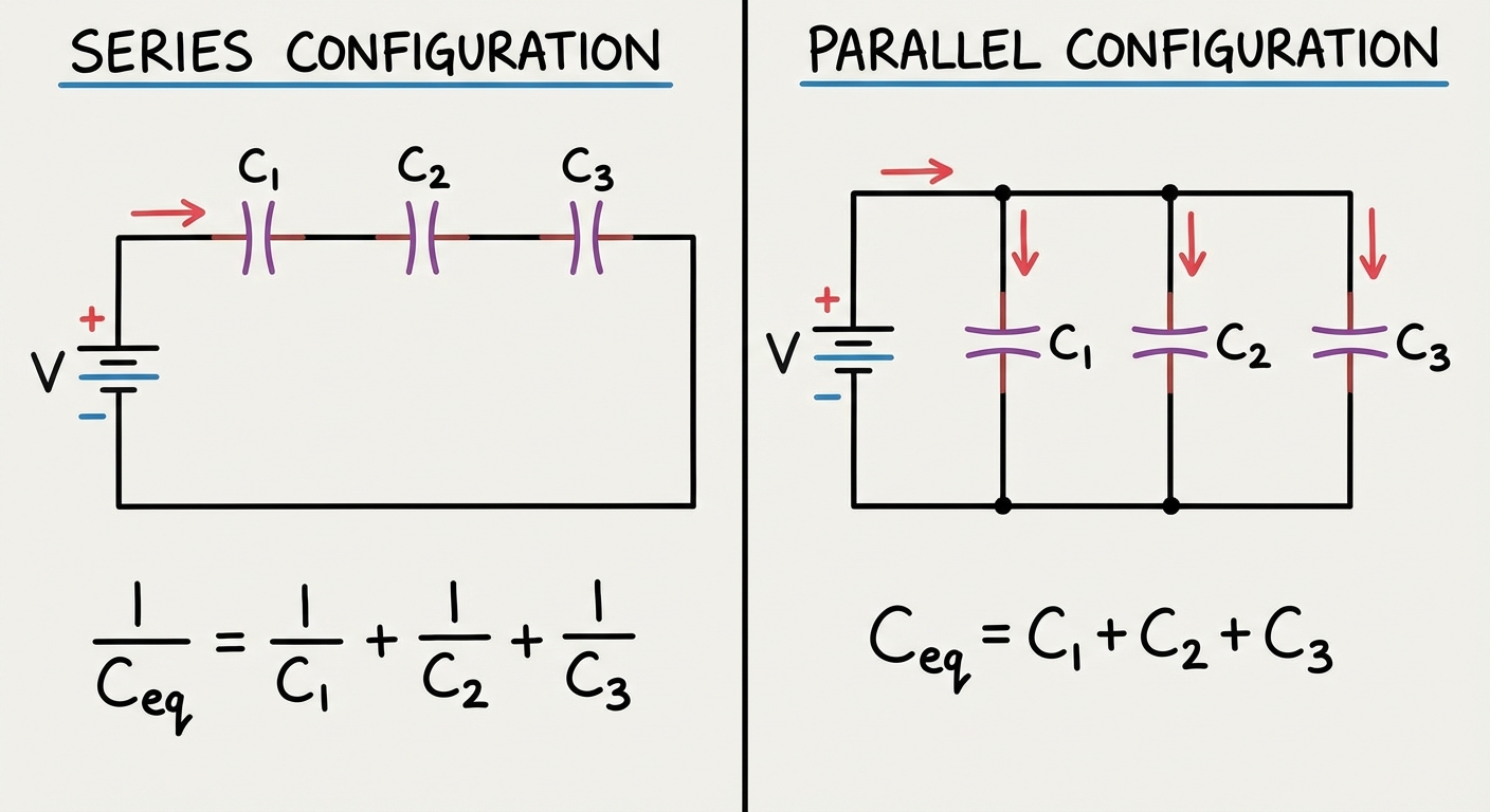
Circuit Configurations for Capacitors
Note that the rules for combining capacitors are the inverse of the rules for combining resistors.
Parallel Capacitors
Connecting capacitors in parallel effectively increases the total plate Area ($A$) available to store charge. Therefore, capacitance increases.
- Voltage: Same across all capacitors ($ΔV1 = \u0394V2 = …$).
- Charge: Splits/Adds up ($Q{total} = Q1 + Q_2 + …$).
- Equivalent Capacitance:
Series Capacitors
Connecting capacitors in series effectively increases the separation distance ($d$) between the extreme outer plates of the combination. Therefore, capacitance decreases.
- Charge: Same on all capacitors due to induction ($Q1 = Q2 = Q_{total}$). The charge pushed off one plate lands on the next.
- Voltage: Splits/Adds up ($\Delta V{total} = \Delta V1 + \Delta V_2 + …$).
- Equivalent Capacitance:
Comparison Table: Resistors vs. Capacitors
| Property | Resistors | Capacitors |
|---|---|---|
| Series Rule | Additive ($R{eq} = \Sigma Ri$) | Reciprocal ($\frac{1}{C{eq}} = \Sigma \frac{1}{Ci}$) |
| Parallel Rule | Reciprocal ($\frac{1}{R{eq}} = \Sigma \frac{1}{Ri}$) | Additive ($C{eq} = \Sigma Ci$) |
| Behavior over time | Constant resistance | Start as short circuit, end as open circuit |
Common Mistakes & Pitfalls
Confusing Resistance and Capacitance Addition Rules
- Mistake: Adding capacitors in series directly like resistors: $C{eq} = C1 + C_2$.
- Correction: Remember basic physics—capacitors in series are "harder" to push charge through (less capacitance). Use the reciprocal formula for series capacitors.
Misunderstanding "Steady State" Voltage
- Mistake: Assuming the voltage across a capacitor always equals the battery voltage at steady state.
- Correction: This is only true if the capacitor is connected directly across the battery or is in a branch parallel to the battery. If the capacitor is in parallel with a resistor $R2$, the capacitor voltage equals the voltage drop across $R2$ ($VC = V{R2}$).
Brightness vs. Current
- Mistake: Thinking that if current decreases, resistance must have decreased.
- Correction: Always use $V=IR$ and Power formulas. Just because a bulb is dimmer (less power) doesn't tell you exactly what happened to $R$ or $V$ without analyzing the full circuit.
Dielectric Insertion
- Mistake: Forgetting conservation of charge.
- Correction: If a battery is disconnected before inserting a dielectric, Charge ($Q$) stays constant, but Voltage ($V$) drops. If the battery remains connected, Voltage ($V$) stays constant, but Charge ($Q$) increases.