Mastering Rotational Motion and Dynamics
The Mechanism of Torque
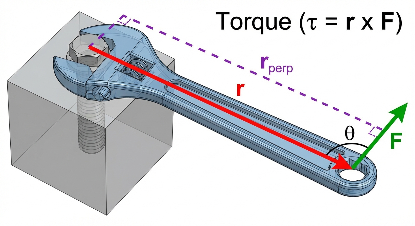
To understand rotation, you must first master the cause of angular acceleration: Torque ($\tau$). Just as force drives linear motion, torque drives rotational motion. In AP Physics C, we move beyond simple multiplication and define torque strictly as a vector product.
The Vector Definition
Torque is defined as the cross product of the position vector ($\vec{r}$) relative to the pivot and the force vector ($\vec{F}$).
Key components:
- Magnitude: $\tau = rF\sin(\theta)$, where $\theta$ is the angle between the position vector and the force vector.
- Direction: Determined by the Right-Hand Rule. Curl your fingers from $\vec{r}$ to $\vec{F}$; your thumb points in the direction of the torque vector (usually perpendicular to the page).
The Lever Arm
An alternative way to calculate torque magnitude is using the lever arm ($r_{\perp}$), which is the perpendicular distance from the axis of rotation to the "line of action" of the force.
This is particularly useful when analyzing static equilibrium problems where geometry allows you to visualize perpendicular distances easily.
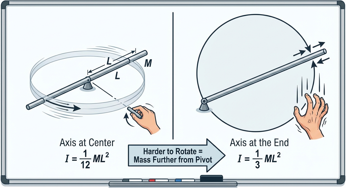
Rotational Inertia (Moment of Inertia)
Rotational Inertia ($I$), often called the Moment of Inertia, is the rotational analog of mass. It represents an object's resistance to changes in its rotational velocity. unlike mass, $I$ depends on how that mass is distributed relative to the axis of rotation.
Discrete Particles
For a system of point masses, rotational inertia is the sum of the products of each mass and the square of its distance from the axis.
Continuous Objects (Calculus Approach)
In AP Physics C: Mechanics, you are expected to derive $I$ for continuous rigid bodies using integration. We treat the object as a collection of infinitesimal mass elements ($dm$).
To solve this, you typically express $dm$ in terms of spatial density:
- Linear: $dm = \lambda \, dr$ (for rods)
- Area: $dm = \sigma \, dA$ (for disks/plates)
- Volume: $dm = \rho \, dV$ (for spheres/cylinders)
The Parallel Axis Theorem
Crucial for solving problems where an object rotates around a point other than its center of mass (COM). If you know the inertia about the COM ($I_{cm}$), the inertia about a parallel axis a distance $d$ away is:
Common Inertias to Memorize:
| Object | Axis | Formula |
|---|---|---|
| Hoop/Shell | Center | $MR^2$ |
| Solid Disk/Cylinder | Center | $\frac{1}{2}MR^2$ |
| Solid Sphere | Center | $\frac{2}{5}MR^2$ |
| Rod | Center | $\frac{1}{12}ML^2$ |
| Rod | End | $\frac{1}{3}ML^2$ |
Newton's Second Law for Rotation
The bridge between kinematics and dynamics in rotation is Newton's Second Law. Just as $\Sigma \vec{F} = m\vec{a}$, for rotation we have:
Where:
- $\Sigma \vec{\tau}_{ext}$ is the net external torque.
- $I$ is the rotational inertia about the axis of rotation.
- $\vec{\alpha}$ is the angular acceleration (rad/s²).
Example: The Massive Pulley
Consider a block of mass $m$ hanging from a string wrapped around a solid disk pulley of mass $M$ and radius $R$. Unlike Physics 1, the pulley has mass, so tension is not uniform if there is friction or inertia on both sides. Here, we analyze the single block system.
- Linear (Block): $mg - T = ma$
- Rotational (Pulley): $\tau = T \cdot R = I\alpha$
- Constraint: $a = R\alpha$ (assuming no slip between string and pulley)
Combining these standard equations allows you to solve for linear acceleration $a$.
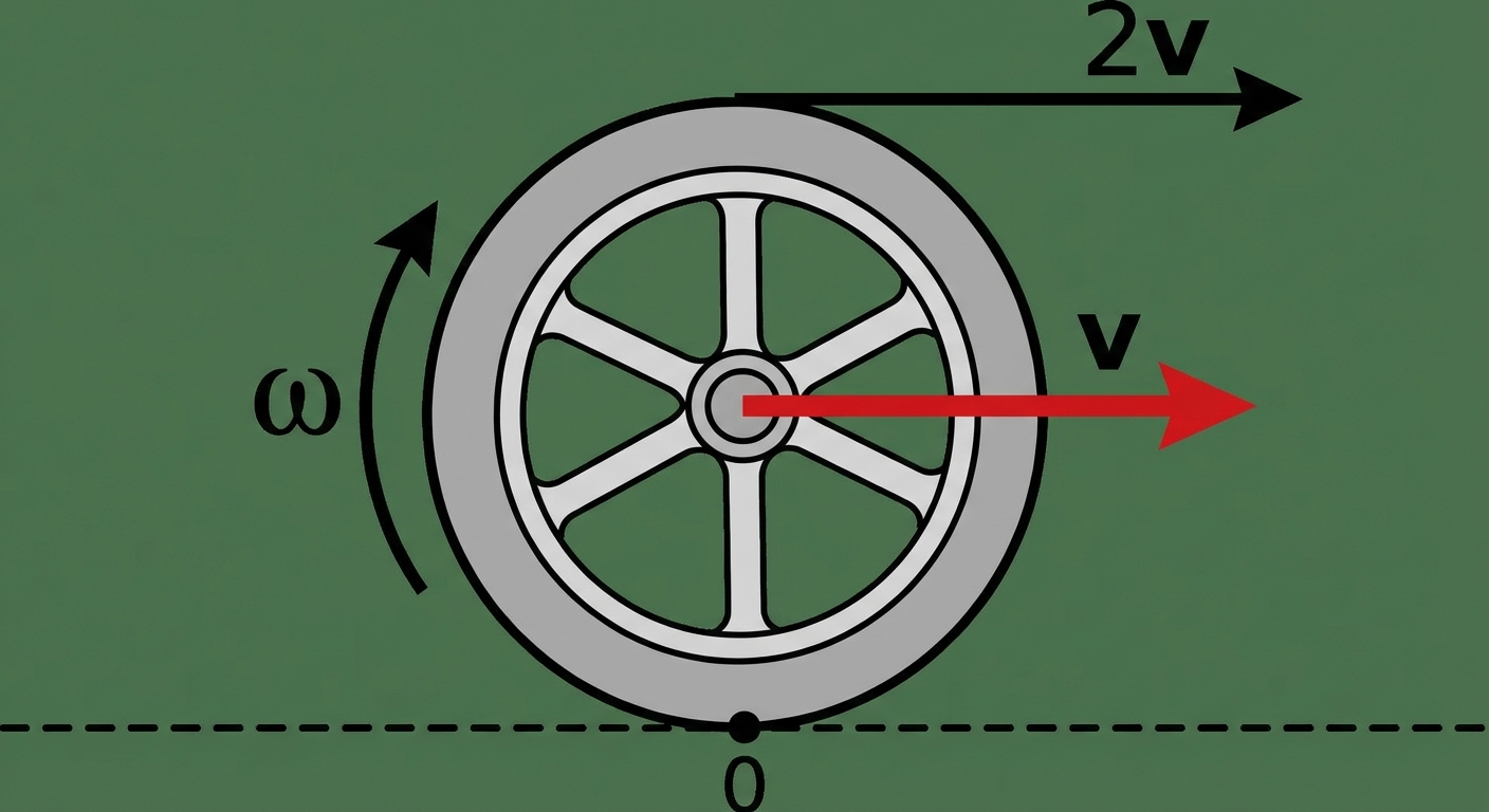
Rolling Motion
Rolling motion combines translational motion of the center of mass and rotational motion around the center of mass.
Condition for Rolling Without Slipping
This is a specific constraint condition where the point of contact between the object and the ground has an instantaneous velocity of zero.
Dynamics of Rolling
When an object rolls down a ramp:
- Static Friction acts at the contact point. It is responsible for providing the torque ($ au{fric} = fs R$) that causes angular acceleration.
- Work by Friction: Surprisingly, in rolling without slipping, static friction does zero mechanical work because the displacement of the contact point is zero at the instant of contact. Therefore, mechanical energy is conserved.
Total Kinetic Energy
The total kinetic energy is the sum of translational and rotational kinetic energies:
Common Mistakes & Pitfalls
- Confusing Axis of Rotation: Students often memorize $I = \frac{1}{3}ML^2$ for a rod and apply it when the rod is actually spinning around its center. Always verify which axis the problem specifies and use the Parallel Axis Theorem if necessary.
- Forces at the Pivot: Remember that forces applied directly at the axis of rotation create zero torque because the lever arm $r=0$. However, these forces still contribute to the linear net force ($\Sigma F$) regarding the center of mass's stability.
- Slipping vs. Tipping: In static problems, check both conditions. An object might slide ($F_f > \mu N$) before it tips, or tip (Torque due to push > Torque due to gravity) before it slides.
- Mixing Units: Always use Radians for logical consistency. $\tau = I\alpha$ only works if $\alpha$ is in rad/s². Degrees must be converted.
- Assuming Friction Always Opposes Motion: In rolling motion (e.g., a car accelerating), static friction at the tires actually points forward to accelerate the car, while the torque opposes the wheel's rotation relative to the axle.